1. Introduction
ircraft structure is example where structural efficiency results in light weight and high operating stresses. The major part of the aircraft structure consists of built-up panels of sheets and stringers, such as wing and fuselage skin panels, spar webs and stiffeners. Despite all precautions, cracks have arisen in many of these structural elements. These cracks reduce the stiffness and the total load carrying capacity of the structure. Thus, they reduce the performance of the aircraft and limit the availability of the aircraft at the time of aircraft maximum performance. The fuselage is the main structure in the aircraft that holds crew, passengers and cargo. An aircraft fuselage structure must be capable of withstanding many types of loads and stresses. The principal source of the stresses in this structure is the internal pressure in high altitude caused by difference of cabin pressurization and reduction of the outside pressure with increase in altitude, but the structure is also subjected to other loads, such as bending, torsion, thermal loads, etc. The aircraft fuselage is composed of the skin consisting of a cylindrical shell typically 2 mm thick, circular frames and axial stringers, and normally these components are manufactured with an aluminium alloy and are connected by rivets. The skin of fuselage is to carry cabin pressure and shear loads, longitudinal to carry the longitudinal tension and compression loads due to bending, circumferential frames to maintain the fuselage shape and redistribute loads into the skin, and bulkheads to carry concentrated loads including those associated with pressurization of the fuselage.
2. II.
3. Literature Review
Fatigue loads in a pressurised fuselage are mostly due to pressure cycles that occur with each takeoff or landing cycle during flight. The most common fatigue crack orientation in a pressurised fuselage is a longitudinal crack along the direction of maximum hoop stress. Damage tolerant designs use fracture mechanics data and analysis to predict crack growth rates and critical crack lengths [1]. Cabin pressure results in radial growth of the skin and this radial growth is resisted by frames and stringers giving local bending along the fastener lines. Fuselage skin panels are curved and these panels are under biaxial tension loading due to cabin pressure. Cabin pressurization is the main source of loading causing longitudinal skin cracks. Two types of damage most frequently associated with the structural integrity of the fuselage are longitudinal cracks under high hoop stresses induced by cabin pressurization and circumferential cracks under stresses from vertical bending of the fuselage. The prime objective was to present a systematic investigation of the damage
A © 2014 Global Journals Inc. (US)Abstract-Transport aircraft is a highly complex airframe structure. The aircraft fuselage shell is composed of stressed skin, circumferential frames and longitudinal stringers. The skin is connected to frames and stringers mostly by rivets. Fuselage has a number of riveted joints and is subjected to a major loading of differential internal pressurization. When the fuselage is pressurized and depressurized during each takeoff and landing cycle of aircraft, the metal skin of fuselage expands and contracts resulting in metal fatigue. Fatigue damage accumulates during every cycle of loading in the airframe structure during its operation. The accumulated damage reaches a critical value, a fatigue cracks initiate from riveted holes and propagate to critical sizes leading to catastrophic failure of the structure. The large transport aircraft are designed to tolerate large fatigue cracks. This paper focuses its attention on damage tolerance design of a fuselage structure of transport aircraft. The objective of this paper is to investigate crack initiation, and crack growth rate in the flat stiffened panel of fuselage structure. The longitudinal crack is initiated from the rivet hole location and stress intensity factor is calculated using modified virtual crack closure integral (MVCCI) method during each stage of crack propagation. Fatigue crack growth rate can be estimated by using Paris law under spectrum loading analysis in the structure. In this paper for modeling CATIA V5 software is used and MSC PATRAN is used for meshing the stiffened panel and static linear stress analysis is carried out using MSCNASTRAN.
tolerance design capability of typical aircraft fuselage structure for longitudinal cracks using linear elastic fracture mechanics [2]. Damage tolerant fuselage is supposed to sustain cracks safely until it is repaired or its economic service life has expired. Strength assessment of the structures is necessary for their in service inspection and repair. Damage tolerance analysis should provide information about the effect of cracks on the strength of the structure. Damage tolerance evaluation must include a determination of the probable locations and modes of the damage due to fatigue, corrosion, or accidental damage. The aircraft must be capable of successfully completing a flight during which likely structural damage occur as a result of bird impact. The crack propagation stage is studied by using stress intensity factor approach [3].
There are different methods used in the numerical fracture mechanics to calculate stress intensity factors (SIF). The crack opening displacement (COD) method and the force method were popular in early applications of FE to fracture analysis. The virtual crack extension (VCE) methods proposed by Parks [5] and Hellen [4] lead to increased accuracy of stress intensity factor results. The virtual crack extension method requires only one complete analysis of a given structure to calculate SIF. Both the COD and VCE methods can be used to calculate SIF for all three fracture modes. The equivalent domain integral method which can be applied to both linear and nonlinear problems renders mode separation possible [6]. The VCCT, originally proposed in 1977 by Rybicki and Kanninen [7], is a very attractive SIF extraction technique because of its good accuracy, a relatively easy algorithm of application capability to calculate SIF for all three fracture modes. Andrzej Leski [8], the implementation of the Virtual Crack Closure Technique in engineering FE calculations. SIF was fundamental quantity that governs the stress field near the crack tip. It depends on the geometrical configuration, crack size and the loading conditions of the body. The stresses are higher in the vicinity of the crack tip, which are characterized by the parameter stress intensity factor. Sethuraman.R and S.K. Maiti [9] have given the mathematical formulae for calculating the stress intensity factor using finite element software tool called as modified virtual crack closure integral technique for mode I. Shamsuzuha Habeeb and K.S. Raju [10] worked on Crack Arrest Capabilities in Adhesively Bonded Skin and Stiffener. The crack arrest capabilities and the load bearing characteristic of a stiffened panel subjected to uniform remote displacement field. Stringers were usually joined to the skin using rivets. Fracture analyses were conducted on stiffened panels with crack tip opening displacement fracture criteria. A linear elastic static stress analysis was performed and the stress intensity factor was calculated for both the stiffened panel for various crack lengths keeping the same loading condition. Fracture occurs when the stress intensity factor reaches a critical value.
The fatigue tests on cracked structures for a range of aircraft aluminium alloys and spectra to reveal a generalized relationship between crack growth and crack size that is consistent with the Frost-Dugdale hypothesis [11], predicted linear relationship between the log of the crack length. The problems that arose when attempting to predict crack growth led to the statement by Newman et al. [12] that, the threshold regime, there is something missing either in the model or the test data is being affected by the load reduction test procedure. Further study is needed to improve the determination of the threshold and near threshold behaviour for metallic materials. The ability of the Frost-Dugdale law to partially overcome these deficiencies is shown in [13] where the law is used to predict crack growth on a cycle by cycle basis in full-scale aircraft fatigue tests. As a structure ages, we frequently encounter the phenomenon of crack/damage growth. Elber and Wolf [14], worked on fatigue crack closure under cyclic tensile loading. The results showed that a fatigue crack can be closed at the crack tip for up to half of the loading amplitude, leaving this portion of the cycle ineffective in propagating the crack. An expression for the crack propagation rate in terms of effective stress amplitude was proposed. This expression was fitted to existing constant amplitude crack data for 2024-T3 aluminum alloy.
4. III.
5. Finite Element Analysis
The finite element method is a numerical technique for solving engineering problems. It is most powerful analysis tool used to solve simple to complicated problems. The pre-processing stage involves the preparation of nodal co-ordinates & its connectivity, meshing the model, load & boundary conditions and material information for finite element models carried in MSC PATRAN described in Fig. 1. The processing stage involves stiffness generation, modification and solution of equations resulting in the evaluation of nodal variables, run in MSC NASTRAN. The post-processing stage deals with the presentation of results, typically the deformed configurations, elemental stresses and forces etc. Mechanical properties of the skin, stiffening members and rivets are required for finite element models. There is little information on the material properties of skin, stiffening members, and rivet material in the literature. Aluminium 2024-T3 and 2117-T4 is used for components fuselage and rivet respectively. Table 1 describes few material properties used for analysis. IV.
6. Stress Analysis of the Stiffened Panel
It involves in pre-processing stage, processing stage and post processing stage. Pre-processing stage involves details of mesh, load & boundary conditions. Pre-processing and post-processing stage is carried in MSC PATRAN. The components of the stiffened panel are meshed by four noded shell elements. Skin of the stiffened panel is meshed by shell elements. Frame of the stiffened panel is meshed by 4 noded and 3 noded shell elements. Fine mesh is carried at mouse hole of frame to get accurate results. Three noded shell elements are used for the sake of continuity from fine mesh region to the coarse mesh region. The rivets are placed on the skin to hold the frames and stringers. Riveting is carried out by selecting the node on the skin and the corresponding node on the other component. Rivets are stimulated by using beam elements indicated in yellow color shown in Fig. 5 & Fig. 6. Aspect ratio should be less than 5 in all components of the stiffened panel. Meshing is checked for any duplicate nodes and elements. Table 2 gives number of elements and element type in the stiffened panel.
7. Global Journal of Researches in Engineering
Where r is the radius of fuselage shell (2000 mm) and t is the thickness of skin (2 mm). After applying these values, we get, the hoop stress 4.2 kg/mm 2 . The radial hoop stresses developed in the fuselage cylindrical shell are equals to tensile stresses of the stiffened panel. The hoop stress developed in the model and corresponding cross sectional area gives the tensile load. This tensile stress is uniformly distributed over the cross section. Uniformly distributed tensile load is applied on the stiffened panel in transverse axial direction. Uniformly distributed load is applied on edges of skin and frame in the transverse direction. But, the stringers are not subjected to any loading, because stringers are passing in longitudinal direction in the stiffened panel. At other end, all the edge nodes of stiffened panel are constrained in all six degree of freedom.
8. c) Stress Contour for skin and frame
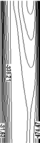
The maximum stress on skin is found at the rivet location where the rivets are used to fasten the frames and stringer on the skin. The tensile stress is uniformly varying from fixed end to loading end. The magnitude of maximum tensile stress is 8.19 kg/mm 2 shown in Fig. 7 at rivet location. The maximum stress locations are the probable locations for crack initiation. Skin is the most critical stress locations for the crack initiation. Generally longitudinal crack is initiated from rivet hole.
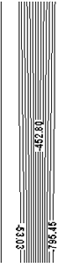
The maximum stresses are induces at mouse hole cut outs and found magnitude of maximum tensile stress is 13.4 kg/mm 2 shown in Fig. 8. This stresses are uniform in all the stringer cut outs. The maximum tensile stress locations are the probable locations for crack initiation. From the stress analysis of the stiffened panel, cracks are initiated from the maximum tensile stress location. There are two structural elements at the rivet location near the high stress location. Even though maximum stresses are found on mouse hole cut outs, cracks are initiated in perpendicular to the loading direction. Skin is the most critical stress locations for crack initiation. So, the maximum tensile stress location on stiffened panel is at skin near the rivet hole. Crack iniation period is studied by using stress concentration factor. Once crack is initiating from rivet location and it linkup with next rivet location, then it become lead crack and finally it leading to catarostrophic failure. Longitudinal crack is initiating from rivet location, which is perpendicular to loading direction. The crack is propagating as a function of number of fatigue cycles due internal pressurization.
The first approximation of the stiffened panel with a centre longitudinal crack is considered for varying crack length in the skin shown in Fig. 9. Crack iniation period is studied by using stress concentration factor, which does not play much important role.
9. Estimation of Fatigue Crack Growth in Stiffened Panel
The crack propagation stage is studied by using stress intensity factor approach. The stress intensity factor plays major role in crack growth period, which is determined by using modified virtual crack closure integral (MVCCI) method. The skin is meshed by four noded shell elements shown in Fig. 10. Fine meshing is carried out near the crack upto crack length of 1000 mm to get crack propagation results. For mesh continuity from fine mesh to coarse mesh different four noded and three noded shell elements are used. The elemental edge length 1.5625 mm is maintained at crack region. Where G i is the energy release rate for mode i, K i is the stress intensity factor for mode i, E is the modulus of elasticity and ? is 1 for plane stress condition.
Calculation of the energy release rate is based on Irwin assumption that the energy released in the process of crack expansion is equal to work required to close the crack to its original state as the crack extends by a small amount Î?" a. Irwin computed this work as (3) Where u is the relative displacement, r is the distance from the crack tip, Î?"a is the change in virtual crack length.
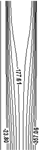
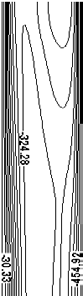
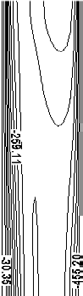
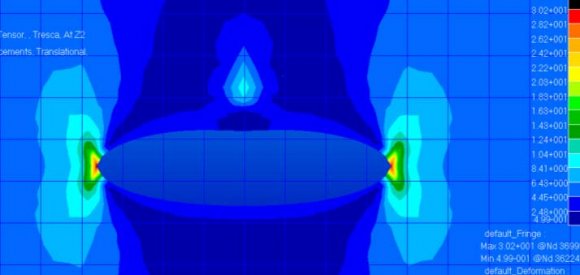
Therefore, the strain energy release rate is (4) After simplification, modified strain energy release rate is Where F is forces at the crack tip, u is crack opening displacement (COD), t is thickness of the skin and a is the elemental edge length nea r the crack tip. The stress intensity factor value at the crack tip can be calculated as follows: (i) Force at the crack tip is calculated by means of adding two elemental forces above the crack tip, and (ii) Crack opening displacement is calculated by means of subtracting the two elemental displacement values at the crack tip. A linear static stress analysis is performed for the stiffened panels for various crack lengths keeping the same loading condition. Figure 11 shows the stress contour for the stiffened panel skin crack. Orientation of crack is in longitudinal direction and crack widens due to loading in transverse direction. The stresses at crack tip are found maximum and its magnitude is 30.2 kg/mm 2 .
The above calculation is carried for different crack length considering a known load. The stress intensity factor value is calculated by using MVCCI method for the stiffened panel. The stress intensity factor is tabulated in steps of 50 mm crack length shown in Table 3. The fatigue strength of a component or structure can be significantly reduced by the presence of a crack or any other sharp discontinuities. More commonly fatigue cracks propagate from the initial to the critical crack size before the final failure occurs. The most common type of sub-critical crack growth is due to fatigue in the presence of an existing crack. In materials science, fatigue is the progressive, localised, and permanent structural damage that occurs when a material is subjected to a cyclic load. In general, the fatigue process is depicted by three distinct regions. Region III is associated with rapid crack growth and as such is typically thought to account for a small fraction of the total life. Region II has received the greatest attention as it is in this region where the ''Paris'' crack growth law [15] can be applied to predict fatigue crack growth propagation. (6) Where, Î?"K is stress intensity factor range under cyclic loads, N is the number of cycles, and C and m are the material constants obtained from experiments. Î?"K is obtained by: (7) The above calculation is carried for different crack length considering a known load. The fatigue crack growth rate and number of cycles is tabulated in steps of 50 mm crack length shown in Table 4.
10. Result and Discussion
From the linear static stress analysis of the stiffened panel has been carried out. A differential internal pressure of 6 psi was considered for the current problem. Fatigue crack propagation stage was studied by using SIF approach for the stiffened panel. Fatigue crack growth rate was calculated using Paris law to predict life of the structure. SIF value was calculated for the stiffened panel with different crack lengths. The maximum stress intensity factor is 39.67 MPa?m found at crack length of 950 mm. There is a decrement in SIF value due to presence of frame at 1000 mm. This plot indicates the frame is able to arrest the further crack propagation.
11. Î?"K
Region I is associated with slow crack growth, region III is associated with rapid crack growth and as such is typically thought to account for a small fraction of the total life. Region II has received the greatest attention to predict crack growth. The presence of two factor in aircraft structures [17]. Fatigue crack growth rate is found 1.405 x 10 -8 mm/cycles for crack length of 50 mm and number of cycles required 71174 cycles for 1mm crack growth. Figure 13 shows Fatigue Crack Growth Rate v/s Stress Intensity Factor Range. Crack growth rate is drastically increases as number of cycles and crack growth rate 3.901 x 10 -7 mm/cycles are found maximum at crack length of 950 mm. Finally crack growth rate is reduces to 3.72 x 10 -7 mm/cycles at frame location [21]. This predicts frame is able to arrest the further crack growth. Figure 14
12. Conclusions
Stress analysis of the stiffened panel was carried out and maximum tensile stress was identified at the rivet hole of skin. Center longitudinal crack was initiated from rivet location of skin. Fatigue crack propagation was estimated by using stress intensity factor approach [22]. Stress intensity factor calculations were carried out for various incremental cracks from 50 mm to 1000 mm. The maximum value of stress intensity factor 39.67 MPa ?m was observed at crack length of 950 mm. The value of stress intensity factor 39.06 MPa?m was observed at frame location. The obtained value of stress intensity factor 39.06 MPa?m at crack length of 1000 mm, which is less than fracture toughness of material 72.37 MPa?m. This can conclude that, frame is able to arrest the crack propagation. Fatigue crack growth rate and stress intensity factor range was estimated with of Paris law of damage crack growth.
VIII.


![C x (?K) m ?K = K ma x -K opening MPa K opening = K max (0.5+ 0.4 R) R = stress ratio = = 0 (since min ?0) Global Journal of Researches in Engineering ( ) A Volume XIV Issue I Version I 16 Year 2014 First step of calculating fatigue crack growth rate [16], For crack length 2a= 50 mm, Stress Intensity Factor Range Î?"K = 6.55 MPa?m, Fatigue Crack Growth Rate = 1.405 x 10⁻⁸ mm/cycle, No. of cycles for crack = 71174 cycles](https://engineeringresearch.org/index.php/GJRE/article/download/978/version/100400/2-Investigation-of-Fatigue_html/8597/image-15.png)
| Property | Aluminium | Aluminium |
| 2024-T3 | 2117-T4 | |
| Density | 2.77 g/cm 3 | 2.77 g/cm 3 |
| Ultimate Tensile Strength | 483 MPa | 490 MPa |
| Tensile Yield Strength | 362 MPa | 350 MPa |
| Young's M odulus | 72 GPa | 71.7 GPa |
| Poisson's Ratio | 0.33 | 0.33 |
| Fracture Toughness | 72.37 MPa?m 76.54 MPa?m | |
| M aterial Constant, C | 5 x 10 -11 | 4x 10 -11 |
| M aterial Constant, n | 3 | 3.2 |
| Product | Type of | No. of | Aspect |
| description | elements | elements | ratio < 5 |
| Skin | QUAD4 | 66820 | 1.00 |
| Frame | QUAD4,TRIA3 | 38428 | 2.12 |
| Stringer | QUAD4 | 42180 | 1.01 |
| Rivet | BEAM | 1340 | -- |
| ? h = |
| ? | |||||
| ? | Crack length | COD ( ?u) in | Elemental forces at | S train energy release rate | S IF, K I FEA |
| ( 2a) in | mm | crack tip | (G) in N/mm | in | |
| mm | (F) in N | MPa?m | |||
| 50 | 0.022 | 695.07 | 2.502 | 13.10 | |
| 100 | 0.029 | 889.29 | 4.142 | 16.86 | |
| 150 | 0.033 | 1026.3 | 5.533 | 19.49 | |
| 200 | 0.036 | 1141.9 | 6.739 | 21.52 | |
| 250 | 0.041 | 1245.5 | 8.172 | 23.69 | |
| 300 | 0.044 | 1340.6 | 9.506 | 25.55 | |
| 350 | 0.045 | 1363.2 | 9.702 | 27.16 | |
| 400 | 0.049 | 1512.4 | 12.08 | 28.79 | |
| 450 | 0.053 | 1590.9 | 13.38 | 30.31 | |
| 500 | 0.055 | 1666.1 | 14.67 | 31.75 | |
| 550 | 0.057 | 1736.5 | 15.96 | 33.11 | |
| 600 | 0.059 | 1802.1 | 17.21 | 34.37 | |
| 650 | 0.062 | 1863.2 | 18.39 | 35.54 | |
| 700 | 0.063 | 1918.3 | 19.50 | 36.60 | |
| Î?" | 750 800 | 0.065 0.066 | 1966.7 2036.4 | 20.51 21.36 | 37.53 38.31 |
| 850 | 0.067 | 2037.3 | 22.02 | 38.89 | |
| 900 | 0.068 | 2058.6 | 22.48 | 39.29 | |
| 950 | 0.069 | 2079.1 | 22.92 | 39.67 | |
| 970 | 0.066 | 2017.8 | 21.39 | 39.14 | |
| 1000 | 0.068 | 2046.7 | 22.22 | 39.06 | |
| K I FEA |
| rate |