1. I.
Introduction ompound cylinders are widely used in the field of high pressure technology such as hydraulic presses, forging presses, power plants, gas storages, chemical and nuclear plants, military applications etc. To enhance load bearing capacity and life of multilayer pressure vessels, different processes such as shrink fit and autofrettage are usually employed. Shrink fit increases load capacity. Many researchers have focused on methods to extend lifetimes of vessels. Majzoobi et al. have proposed the optimization of bimetal compound cylinders and minimized the weight of compound cylinder for a specific pressure [1]. The variables were shrinkage radius and shrinkage tolerance. Patil S. A. has introduced optimum design of two layer compound cylinder and optimized intermediate, outer diameter and shrinkage tolerance to get minimum volume of two layer compound cylinders [2]- [3]. Hamid Jahed et al. have investigated the optimum design of a three-layered vessel for maximum fatigue life expectancy under the combined effects of autofrettage and shrink fit [4]. Miraje Ayub A. & Patil Sunil A. have found minimum volume of three-layer open type compound cylinder considering plane stress hypothesis [5]. Yang Qiu-Ming et al. have presented a simple and visual tool to calculate the residual stress and describe the distribution of residual stress for both the elastic-perfectly plastic model and the strainhardening mode [6].
2. II.
3. Analytical Approach
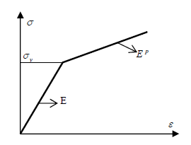
As stated earlier, an elasto-plastic behavior has been designated in this work. (1)
In which, ? is the effective stress, ? y is the initial yield stress, E p is the slope of the strain hardening segment of stress strain curve, and ? is the effective strain.
4. a) Tangential & Radial Stress Pattern
To observe the stress pattern in a compound cylinder, a sample cylinder with internal diameter a = 0.1m, interference radius c = 0.15m, and external radius b = 0.20m has been considered. Material Properties of this cylinder summarized in table I Table 1 : Material Properties An outer cylinder with the internal diameter slightly smaller than the outer diameter of the main cylinder is heated and fitted onto the main cylinder. When the assembly cools down to room temperature a compound cylinder isobtained. In this process the main cylinder is subjected to an external pressure leading to a compressive radial stress at the interface. The outer cylinder or the jacket is subjected to an internal pressure leading to a tensile circumferential stress at the inner wall. Under this condition as the internal pressure increases the compression in the inner cylinder is first released and then only the cylinder begins to act in tension. Though outer cylinder is fitted on the top of the inner cylinder, a compressive stress is developed in the near bore region. Here in the fig. 2, compressive stress is developed in the inner diameter while tensile stress occurs at the outer portion. Here the initial stress is compressive so if internal pressure is applied, then a tensile stress will be developed & this tensile stress even quite high, but the resultant stress not that high because of this compressive stress.
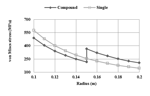
5. Comparison of Stress between Single cylinder & Compound Cylinder
By using Lame's equation for thick-walled cylinder, the stress pattern is obtained for both single cylinder & compound cylinder. If these two cylinders undergoes same internal pressure then the overall stress pattern will change, which is shown in Fig. 3, here the internal pressure is 250 MPa. The equivalent stress based on the fourth strength theory is as follows [12[-[13]: 2), we obtain: ? From third strength theory, MVS = 666 MPa
(3) ( ) A Year 013 2 r t III eq ? ? ? ? ? ? ? ? ? ? ? ? ? 2 2 2 2 1 t z z r r t IV eq ? ? ? ? ? ? ? ? ? ? ? ? ? Substituting (Lame formula) Eq.(2 / ) ( r t z ? ? ? ? ? ume XIII Issue XI Version I b) (4) III eq r t IV eq ? ? ? ? 2 3 ) ( 2 3 ? ? ?? From fourth strength theory, MVS =577 MPa
? From these two theories, it is observed that MVS for both is very similar. Indeed there is no significant variation between these two methods.
? Fourth strength theory is considered for all comparison.
III.
6. Numerical Result
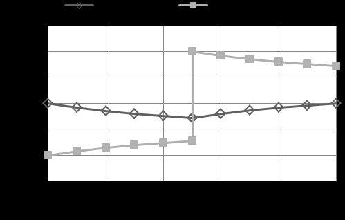
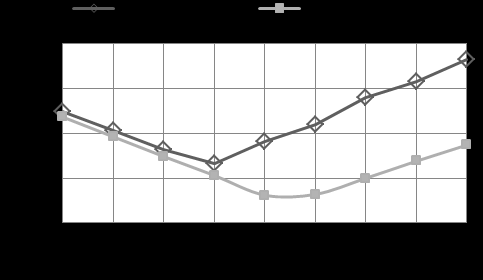
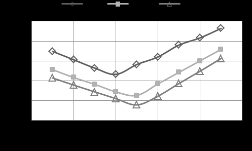
The compounding process may be simulated by Finite Element Method, making use of elastic-plastic The cylinders were subjected to different internal pressures of 100, 200 and 300 MPa. From the numerical simulation with ANSYS software, the curve of the von Mises stress distribution was obtained for each working pressure. From the curve, the values of maximum von Mises stresses (MVS) were extracted. This stresses were then plotted against interference radius for each working pressure. The results are shown in fig. 6. It is observed that with the increase of interference radius, the MVS decreases slightly. Because at small interference radius, lower contact pressure is developed at the junction of the two cylinders. When the radius increases then the contact pressure increases and there is much compressive stress at the inner bore region resulting lower MVS. With the increase of interference radius much stress is developed at the outer cylinder; resulting a higher overall stress distribution.
The value of MVS is calculated for different interference radius for different working pressures. For a constant value of interference radius (280 mm) the percent reduction of MVS is calculated for different working pressure. From the table III, it is observed that the percent reduction of MVS is higher at moderate & higher working pressures.
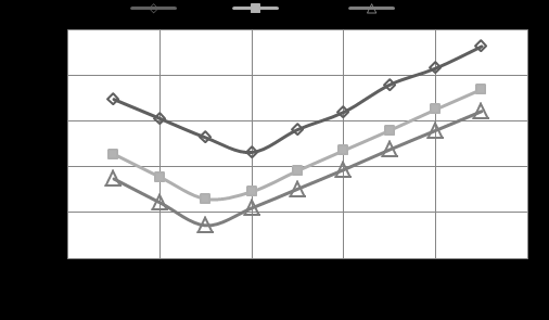
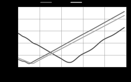
7. b) Change of Shrinkage Tolerance
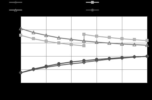
In the preceding case minimum MVS was found in between 280 mm & 300 mm of interference radius. Now the cylinder is subjected to a working pressure 200 MPa and interference radius is considered as 280 mm. From the curve, the values of maximum von Mises stress (MVS) are extracted. This stresses are then plotted against the shrinkage tolerance. The results are shown in fig. 8. As in fig. 9, suggests for different values of k, the minimum MVS obtains a higher value of thicker cylinder at lower diametral interference.
For a constant working pressure (Pworking = 200 MPa), percent reduction of MVS is calculated for different k values.
8. Table 4 : Effect Of K = (B/A) On Mvs At Constant Inner
9. Radius
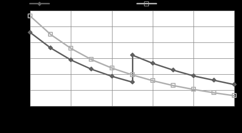
From table IV, it is observed that, percent reduction of MVS is higher for higher value of k. So, the process is more beneficial with the increase of the thickness of the cylinder. ? Constant outer diameter In the preceding case the inner radius of the inner cylinder was kept constant. Now by assuming the outer radius (b= 0.2m) constant, cylinder with three k values of 2.0, 2.5, 3.0m are considered. From the numerical simulation, the curve of MVS distribution is obtained for each value. The developed MVS are then plotted against diametreal interference at fig. 10 . From above two graphs it can be said that, constant inner radius of inner cylinder is more effective than other one. Because in inner radius constant process the minimum von Mises stress found i n lower diametral interference. From fig. 12, it is noticed that, these two metals jacketed by steel work better at small diametral interference.
IV.
10. Conclusion
The following decisions can be taken from the investigations mentioned in this paper:
1. In compound cylinder, maximum von Mises stress does not occur at smaller interference radius instead of that, it occurs at midway section.
2. Maximum stress depends on the interference radius as well as diametral interference.
3. The optimum diametral interference depends on k value only rather than inner & outer radius.
4. The thicker the cylinder the more will be the reduction in MVS.
5. Two element cylinder of different material reduces diametral interference more than two element cylinder of same material.
ume XIII Issue XI Version I 6. The size of a compound cylinder could be reduced by significant amount with respect to its equivalent single cylinder for the same working pressure.
7. The difference between a compound cylinder and its equivalent single cylinder becomes more significant at higher working pressures.

| 013 | |||
| 2 | |||
| Year | |||
| Radius for Different Working Pressure | |||
| Interference | Pressure | Pressure | Pressure |
| Radius (mm) | 100 (MPa) | 200 (MPa) | 300 (MPa) |
| 240 | 203 | 386 | 576 |
| 260 | 190 | 379 | 569 |
| 280 | 191 | 366 | 558 |
| 300 | 184 | 369 | 554 |
| 320 | 193 | 375 | 568 |
| 340 | 195 | 390 | 604 |
| From the table II, it is observed that the | |||
| minimum values of MVS are at 280 mm & 300 mm. This | |||
| means in those radius tangential stresses at inner wall of | |||
| inner cylinder and inner wall of outer cylinder almost | |||
| same. | |||
| I | |||
| ume XIII Issue XI Version | |||
| Mises Stress | |||
| Working Pressure (MPa) | MVS of single (MPa) cylinder | MVS of compound (MPa) cylinder | % reduction of MVS |
| 100 | 233 | 191 | 18.03 |
| 200 | 467 | 366 | 21.63 |
| 300 | 701 | 558 | 20.40 |