1.
Introduction n electrical drive, as shown in Fig. 1.1 can be defined in terms of its ability to efficiently convert energy from an electrical power source to a mechanical load. The main purpose of the drive is to control a mechanical load or process. The direction of energy flow is generally from electrical to mechanical i.e. motoring mode with power flow from the power source to the mechanical load via the converter and machine as shown in Fig. 1.1. However the energy flow can be reversed in some cases, in that case the drive often is configured bi-directional to allow energy flow from the mechanical load to the power source. Modern electrical drives as considered utilize power electronic devices to (digitally) control this power conversion process. A feature which is highlighted in Fig. 1.1 by the presence of the modulator and control unit The controller module shown in Fig. 1.1 must be able to communicate with higher level computer systems because drives are progressively networked. Communication links to high level computer networks are required to support a range of functions, such as commissioning, initialization, diagnostics and higher level process control.
The embedded digital controller shown in Fig. 1.1 houses the high-speed logic devices, processors and electronic circuitry needed to accommodate the sensor signals derived from mechanical and electrical sensors. Further the most suitable control algorithms must be developed to facilitate the power conversion processes within the drive. With the advent of new materials and new design tools, novel machine concepts such as linear machines, PM magnet, switched reluctance and transversal flux machines etc. have been developed over the past twenty years. Power electronic devices have on the other hand been around for about forty five years, while high-speed digital devices have only been available over the past twenty five years.
2. PMSM rive Scheme
Permanent Magnet Synchronous Machines are being increasingly used in industrial applications because of the many advantages they present over the other types of machines. These machines are compact and have very high efficiency, and the drives associated are well developed and reliable. However, the main drawback for these drives is the need for an accurate knowledge of the rotor position to achieve the most efficient drive.
An optical encoder usually ensures this accurate knowledge of the shaft position. This encoder introduces extra cost, extra wiring leading to a decrease in the overall reliability of the drive. One particular type of PMSM known as Brushless Direct Current (BLDC) machine uses three or fewer low-resolution sensors to operate, and has trapezoidal waveforms. Nevertheless these machines have a non-negligible torque ripple. In applications where a smooth torque profile is required or where vibrations have to be low these machines cannot replace the sinusoidal PMSM.
Numerous researches have been conducted to eliminate the encoder in PMSM drives and it is necessary to find among them a realistic sensorless method whose implementation is feasible for a defined set of industrial applications, taking into account its complexity and reliability.
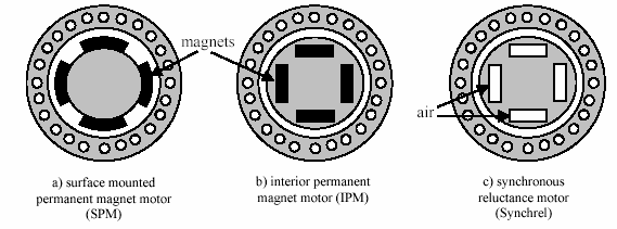
One can find various names for the same motor based on different approaches or points of view. Brushless synchronous AC motors are one type of synchronous motor. Synchronous AC motors are sinusoidal current-driven machines that use a quasisinusoidal distributed AC stator winding and inverter. The three main types are shown in Figure 2. Figure 2. (a) Shows the cross-section of a surface-mounted PMmotor (SMPM). Radial or straight-through magnetized permanent magnets are fixed to an iron rotor core. The magnets are normally glued to the rotor surface. Due to its isotropic rotor, the d-and q-axis inductances are identical.
Figure 2 : Cross section of the three main types of PMSM Therefore no reluctance torque occurs. In Figure 2.2b, a possible design of an interior permanent magnet motor (IPM) is presented in which the magnets are buried in the rotor core. Setting the magnets inside the rotor improves the mechanical strength and magnetic protection. An IPM motor exhibits both magnetic and reluctance torque. These features allow the PMSM drive to be operated in high-speed mode by incorporating the field -weakening technique. Figure 2.2c shows the cross-section of a synchronous reluctance motor. Without permanent magnets, the reluctance motor produces only reluctance torque.
3. III.
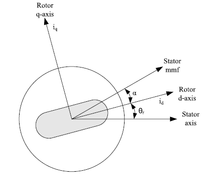
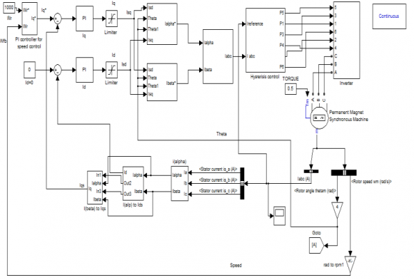
Detailed Modelling of PMSM Detailed modeling of PM motor drive system is required for proper simulation of the system. The d-q model has been developed on rotor reference frame as shown in Fig. 3. At any time t, the rotating rotor d-axis makes and angle ?r with the fixed stator phase axis and rotating stator mmf makes an angle ? with the rotor daxis. Stator mmf rotates at the same speed as that of the rotor. Substituting equations ( 3) and ( 4) into ( 1) and ( 2)
(5)(6)© 2013 Global Journals Inc. (US)
4. Global Journal of Researches in Engineering
Modelling, Simulation of Permanent Magnet Synchronous Machine Drive using FOC Technique
q d r q s q w i R v ?? ? ? ? ? d q r d s d w i R v ?? ? ? ? ? q q q i L ? ? f d d d i L ? ? ? ? ? q f d d r q s q i L w i R v ?? ? ? ? ? ? ) ( ) ( f d d q q r d s d i L i L w i R v ? ? ? ? ? ? Volume XIII Issue IX Version I 22 ( ) A Year 013 25. D
Arranging equations ( 5) and ( 6) in matrix form (7) The developed motor torque is being given by ( 8)
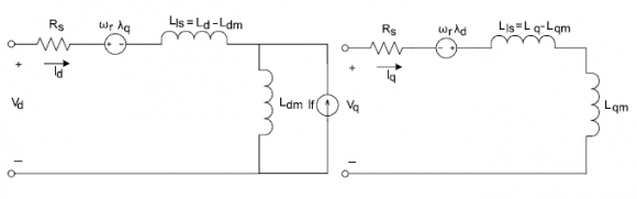
IV.Equivalent Circuit of Permanent Magnet Synchronous Motor
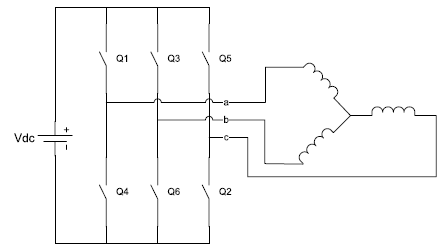
6. Current Controlled Voltage Source Inverter
The motor is fed form a voltage source inverter with current control.
? ? ? ? ? ? ? ? ? ? ? ? ? ? ? ? ? ? ? ? ? ? ? ? ? ? ? ? ? ? ? ? ? ? ? ? ? f r r d q d s q r d r d s d q w i i L R L w L w L R v v ?? ? ? ? ? ? d q q d e i i P T ? ? ? ? ? ? ? ? ? ? 2 2 3Equivalent circuit of the motor is used for study and simulation of motor. From the d-q modelling of the motor using the stator voltage equations the equivalent circuit of the motor can be derived. Assuming rotor d axis flux from the permanent magnets is represented by a constant current source.
7. VI.
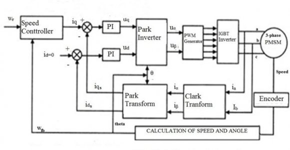
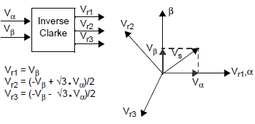
8. Coordinate Transforms
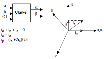
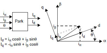
Through a series of coordinate transforms determine and control the time invariant values of torque and flux with classic PI control loops. The process begins by measuring the 3-phase motor currents. The instantaneous sum of the three current values is zero. Therefore by measuring only two of the three currents we can determine the third. Because of this fact hardware cost can be reduced by the expense of the third current sensor.
9. a) Clarke Transform
The first coordinate transform, called the Clarke Transform, moves a three-axis, two-dimensional coordinate system, referenced to the stator, onto a twoaxis system, keeping the same reference.
10. Current Control Technique
The power converter in a high-performance motor drive used in motion control essentially functions as a power amplifier, reproducing the low power level control signals generated in the field orientation controller at power levels appropriate for driving the machine. High-performance drives utilize control strategies which develop command signals for the AC machine currents. The basic reason for the selection of current as the controlled variable is the same as for the DC machine; the stator dynamics (effects of stator resistance, stator inductance, and induced EMF) are eliminated. Thus, to the extent current regulatory functions as an ideal current supply, the order of the system under control is reduced and the complexity of the controller can be significantly simplified.
Current regulators for AC drives are complex because an AC current regulator must control both the amplitude and phase of the stator current. The AC drive current regulator forms the inner loop of the overall motion controller. As such it must have the widest bandwidth in the system and must by necessity have zero or nearly zero steady-state error.
Both current source inverters (CSI) and voltage source inverters (VSI) can be operated in controlled current modes. The current source inverter is a "natural" current supply and can readily be adapted to controlled current operation. The voltage source inverter requires more complexity in the current regulator but offers much higher bandwidth and elimination of current harmonics as compared to the CSI and is almost exclusively used for motion control applications.
11. Global Journal of Researches in Engineering
( )
A © 2013 Global Journals Inc. (US)Modelling, Simulation of Permanent Magnet Synchronous Machine Drive using FOC Technique VIII.
12. Hysteresis Current Controller
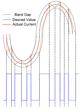
Hysteresis current controller can also be implemented to control the inverter currents. The controller will generate the reference currents with the inverter within a range which is fixed by the width of the band gap. In this controller the desired current of a given phase is summed with the negative of the measured current. The error is fed to a comparator having a hysteresis band. When the error crosses the lower limit of the hysteresis band, the upper switch of the inverter leg is turned on. But when the current attempts to become less than the upper reference band, the bottom switch is turned on. Fig. 10 shows the hysteresis band with the actual current and the resulting gate signals. This controller does not have a specific switching frequency and changes continuously but it is related with the band width.
13. Testing and Experimental Result
In college laboratory set up, we are using different controller and STM32F103 Processor is used for the control signal generation and these control signals are given to the 3-Phase IPM module. This chapter illustrates different experimental results Experimental Results:
14. Conclusion
This paper covers major issues and solutions dealing with sensorless Field Orientation control of permanent magnet synchronous motor (PMSM) over wide speed range in constant torque region. A constant torque control technique has been implemented and the following conclusions can be drawn.
Moreover no saturation of current controller occurs under load conditions, resulting in control robustness in the constant torque region. A single shunt current sensing measurement has been developed for the estimation of rotor position angle in the sensorless Field Orientation Control of PMSM without saliency. Compared to conventional sliding mode observers, the proposed scheme has the feature which gives the flexibility to design parameters of single shunt current measurement with wide operating speed range.

| 6 | 244.2 | |
| 1600 | 1.6 | 230.4 |
| 1600 | 1.6 | 210.2 |
| 1400 | 1.6 | 194.1 |
| 1300 | 1.6 | 180 |
| 1200 | 1.6 | 169.3 |
| 1100 | 1.6 | 166.4 |
| 1000 | 1.6 | 144.3 |
| 900 | 1.6 | 130 |
| 800 | 1.6 | 111.2 |
| 700 | 1.6 | 100.2 |
| 600 | 1.6 | 90.26 |