1. Introduction
icrostrip patch antennas are popular for their well-known attractive features of low profile, light weight, and compatibility with monolithic microwave integrated circuits (MMICs). Because of their attractive feature they are in great demand in wireless communication applications. The main disadvantage of this microstrip antenna narrow bandwidth, which is due to the resonant nature of the patch structure. [4] Conventional microstrip antennas in general have a conducting patch printed on a grounded microwave substrate, and have the attractive features of low profile, light weight, easy fabrication, and conformability to mounting hosts. [1] However, conventional microstrip patch antenna suffers from very narrow bandwidth, typically about 5% bandwidth with respect to the center frequency. This poses a design challenge for the microstrip antenna designer to meet the broadband techniques [3]. To overcome this problem of narrow bandwidth, many proposals and techniques have been analyzed and investigated such as probe fed stacked antenna, microstrip patch antennas on electrically thick substrate, slotted patch antenna and stacked shorted patches, the use of various impedance matching and feeding techniques, the use of multiple resonators. [14] The development of antenna for wireless communication also requires an antenna with more than one operating frequency. This is due to many reasons, mainly because there are various wireless communication systems and many telecommunication operators using various frequencies. Therefore one antenna that has multiband characteristic is more desirable than having one antenna for each frequency band. [7] Our aim is to increase the operating bandwidth the simulation has been carried out by IE3D. So we want an antenna which offers a low profile, wide bandwidth, compact antenna element. Among these standards, the following frequency bands can be mentioned: (1) PCS-1900 requires a band of 1.85-1.99 GHz; (2) IEEE 802.11b/g requires a band of 2.4-2.484 GHz; (3) IEEE 802.11a requires a band of 5. 15-5.35 GHz and an additional band of 5.725-5.825 GHz; (4) HiperLAN2 requires a band of 5.47-5.725 GHz besides the band of 5.15-5.35 GHz. [2,6,7,12] To overcome the above problem, a microstrip antenna structure with a typical Kite symbol shaped patch is proposed which exhibits good enhanced impedance bandwidth of up to 76.53% depending upon the radius of probe.
2. II.
3. Antenna Design
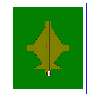
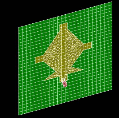
The dielectric constant of the substrate is closely related to the size and the bandwidth of the microstrip antenna. Low dielectric constant of the substrate produces larger bandwidth, The resonant frequency of microstrip antenna and the size of the radiation patch can be similar to the following formulas while the high dielectric constant of the substrate results in smaller size of antenna [1].The Length of ground plane of Antenna is 24 mm and Width is 28.2 mm, L & W of the patch is 14 mm & 18.6 mm the radius of the coaxial probe feed is taken as 0.5 mm. The material used for substrate is glass epoxy with dielectric constant of 4.2, loss tangent .0012 and substrate height of 1.6 mm. The proposed structure is shown in fig 1 . The patch width, effective dielectric constant, the length extension and also patch length are given by
r f c W ? 2 = (1)where c is the velocity of light, r ? is the dielectric constant of substrate, f is the antenna working frequency, W is the patch non resonant width, and the effective dielectric constant is eff ? given as, ( ) ( )
2 1 10 1 2 1 2 1 ? ? ? ? ? ? ? + ? + + = W H r r eff ? ? ? (2) M I 13 ( )4. Year
The extension length ? is calculates as, ( )
( ) ? ? ? ? ? ? + ? ? ? ? ? ? ? + + = ?5. Simulated Results
In If the radius of the probe is decreased from 0.5 mm to 0.4 mm dramatically changes will appear in the result. We can see the details given in table 1, we are getting three bands of frequency in first structure when radius is 0.5 mm but when we decrease the radius we get two band in which we get the bandwidth of 36.25% in first band and 56.16% in the second band the max.
Gain remains the same in band 1 as in the previous case but in band two the max. Gain is reduced by only 0.5 dBi. Max. Efficiency remains almost same and max. Directivity is around 6.5 dBi. Now if we further decrease the radius of probe from 0.4 mm to 0.16 mm (sl.no.3, fig. 1) we achieve impedance bandwidth of 76.53 % which is almost double the frequency in the first stage when radius of the probe is 0.5 mm with max. Gain of 3.5 dBi, efficiency 90 % and max. Directivity of 5.5 dBi.
6. Serial
No.
7. Radius of probe
8. Conclusion
In this paper a compact size microstrip antenna has been designed having good impedance matching as well as high antenna efficiency of about of about 90% is achieved by changing the radius of the probe. The impedance band width has been enhanced from 39 % to 76.53 %. The proposed antenna have larger impedance bandwidth of 76.53% covering the frequency range from 3.362 GHz -7.53 GHz which is suitable for WLAN (upper band application).

| Band of Freq. | %Bandwidth | Max. Gain | % Efficiency | Max. Directivity | ||
| (in GHz) | ||||||
| 1 | 0.5 mm | 3.208 -4.763 | 39.02 % | 3.5 dBi | 90% | |
| 4.853 -5.293 | 8.67 % | 3.5 dBi | 65 % | 6.75 dBi | ||
| 6.029 -8.533 | 3.39 % | 4.5 dBi | 65 % | |||
| 2 | 0.4 mm | 3.189 -4.601 | 36.25 % | 3.5 dBi | 90 % | 6.5 dBi |
| 4.655 -8.29 | 56.16 % | 4.0 dBi | 75 % | |||
| 3 | 0.16 mm | 3.362 -7.53 | 76.53 % | 3.5 dBi | 90 % | 5.5 dBi |