1. Introduction
ommunication between humans was first by sound through voice. With the desire for slightly more distance communication came, devices such as drums, then, visual methods such as signal flags and smoke signals were used. These optical communication devices, of course, utilized the light portion of the electromagnetic spectrum. It has been only very recent in human history that the electromagnetic spectrum, outside the visible region, has been employed for communication, through the use of radio. One of humankind's greatest natural resources is the electromagnetic spectrum and the antenna has been instrumental in harnessing this resource.
Many wireless service providers have discussed the adoption of polarization, diversity and frequency diversity schemes in place of space diversity approach to take advantage of the limited frequency spectra available for communication [1][2][3][4][5][6][7][8][9][10]. Due to the rapid development in the field of satellite and wireless communication there has been a great demand for low cost minimal weight, compact low profile antennas that are capable of maintaining high performance over a large spectrum of frequencies. Through the years, microstrip antenna structures are the most common option used to realize millimeter wave monolithic integrated circuits for microwave, radar and communication purposes . Compact microstrip antennas capable of dual polarized radiation are very suitable for applications in wireless communication systems that demand frequency reuse and polarization diversity.
2. a) Aim and Objective
The main aim of this paper to provide the very efficient bandwidth and return loss. For achieving this we designed many Microstrip antenna and obtained good results. If bandwidth is good then it can be used to any type of application. In here my work defines that at different feed points [41,42] we can get a useful bandwidth where we can use the different devices. The performance comparison is based on, return loss, and bandwidth at all four different feed points in first MSA. In second patch we have simulate the patch at 4GHz, 5GHz, and 6GHz frequency and we find wideband width. And in third patch [37,39] describe the phenomena of dual band.
3. II.
Dimensions Calculation of 1 st Proposed Antenna The width of the Microstrip patch antenna [36] is given by equation (1) as:
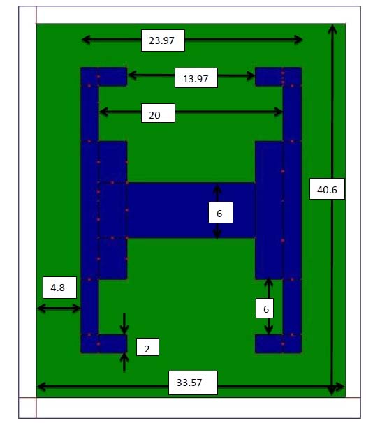
W = ?? 2f r ? ? r +1 2(1)Substituting c = 3e8 m/s, ? r = 4. The transmission line model is applicable to infinite ground planes only. However, for practical considerations, it is essential to have a finite ground plane. It has been shown by [9] that similar results for finite and infinite ground plane can be obtained if the size of the ground plane is greater than the patch dimensions by approximately six times the substrate thickness all around the periphery. Hence, for this design, the ground plane dimensions would be given as:
L g = 6h + L = 6(1.6) + 23.97 = 33.57mm(6)F max and F min are frequency is maximum and minimum frequency at below -10db .In here F max = 2.691GHz F min = 2.054 we get B(%) = 26.84%.
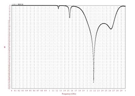
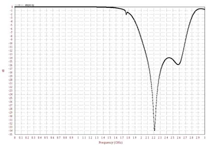
Similarly for each feed point we can calculate the bandwidth of the patch. Now form the above results we conclude that the proposed antenna give the various results at different feed points ,and all the results are useful for communication field without changing any other parameter we have found the useful results at all the feed points. At the 2 nd feed point we have getting the best results in all others the feed points. From the above given table we can see that return loss is goes below -10 db at frequency 2.10GHzand the maximum return Loss is obtained at frequency 2.32GHz is-41db. Return loss again goes above -10db at frequency 2.65GHz.
So from here we can calculate the bandwidth of patch at second feed point, because we test these patch at second feed point.
Band width (%) = 2.65?2.10 2.65+2. 10 2 × 100= 23.15%
In the simulation we have find out these bandwidth is 31.25% between frequency 1.979 GHz to 2.71GHz and return loss is -51db.But as we already consider that due to various effects these results can be vary. But if we optimized then we can get more effective results.
In the given table comparison is shown between simulated and actual testing results
4. Table 2 : Comparisons between Simulated and Testing
5. Results
6. Specifications
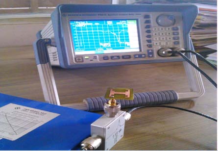
Testing Results
7. Simulation results
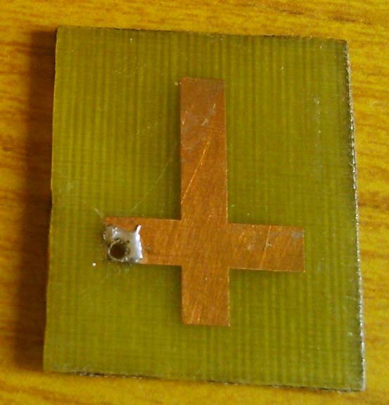
Return Loss -41 -51 Band width (%) 23.15 31.25 h) Inverted T Shape Microstrip Antenna [43,44,45] As we know the main drawback of microstrip patch antenna is its narrow bandwidth but it can be improved by various techniques. In here we are taking a patch and we simulate it 4GHz, 5GHz and 6GHz frequency and we observe that when we goes to higher frequency its bandwidth is improved. And at 6GHz we also obtained dual bandwidth. So our main work in here to improve the bandwidth of the patch by allocating the feed point at same location.
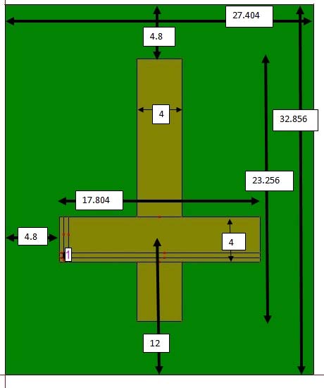
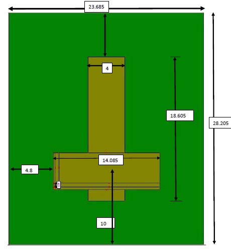
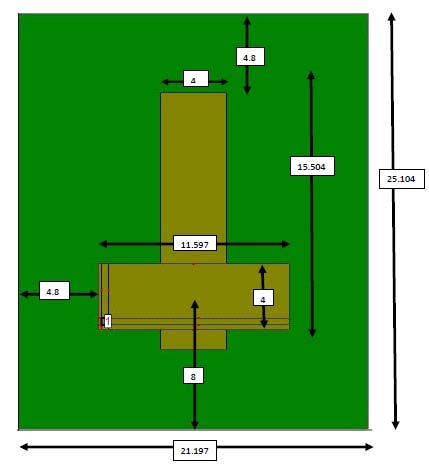
From the above formulas in we can calculate the W and L of the patch for different frequencies, table 4.4 are given below for the W and L. In this work we are having the three same type of patch, but for each patch W and L are change because frequency for each patch are change. But in here we are shown the entire patch at 4GHz, 5GHz and 6GHz A proposed inverted T shapes patch is analyzed with a 4GHz, 5GHz, and 6GHz. This is found that by varying the operating frequency the size of patch changed [table. 4.4] and a result is also changed [table .]. At 4GHz, 5GHz, 6GHz frequencies antenna parameters return loss, bandwidth are measured and compared.
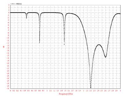
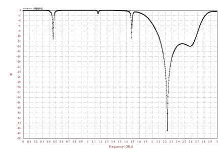
At 4GHz frequency we take a feed point at X= 5.425 and Y= 10.625, in here we are using a coaxial probe feed. From the results we conclude that the return loss is maximum at 4GHz And the minimum, return loss is at 6GHz.When we conclude the bandwidth of the patch then maximum bandwidth is 50%, obtained at 5GHz and minimum bandwidth is 42.42% at 4GHz (accept 1 st band at 6GHz).The main important result in here is dual bandwidth is obtained at 6GHz, which can be used in various application. In the above work we have found that by changing the operating frequency and keeping feed point area constant, it is seen that as bandwidth is improves. We are getting single band at 4GHz and5 GHz while as at 6GHz we obtained dual band of 4.74% and 47%. It suggests that the microstrip antenna performance can be upgraded by using the proposed inverted T shaped patch antenna. The main focus is our work, that we are not changing the feed point area. By our work compactness of microstrip patch antenna can be achieved. Return loss is a measure of the reflected energy from a transmitted signal which is commonly expressed in positive dB. The larger the value the lesser is the energy that is reflected. From the figure we can see that dual band width is obtained. The first Band at frequency between 1.87GHz -2.08GHz, and the maximum return loss at here is -26db. From this band we can find out the 10.63% bandwidth by using fallowing equation.
The second band of this microstrip antenna, we are obtain at frequency range 2.3GHz-3.0GHz and maximum return loss is here -20db and the bandwidth is 26.41%.The return loss should be -10db is satisfactory for this patch to provide better results.
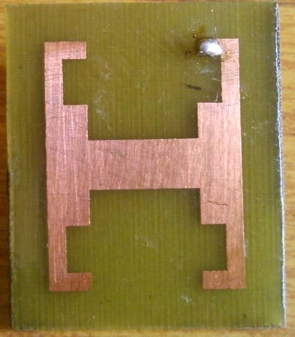
But when we actually test this patch then we obtain some changes in results. The return loss of first band is obtained same as simulation but return loss of second band is goes to -32db.s III.
8. Conclusion
We have designed various novel wideband microstrip patch antennas. The characteristics of proposed antennas have been investigated through different parametric studies using IE3D simulation software. The proposed antennas have achieved good impedance matching, stable radiation patterns, and high gain. The work in this paper primarily focuses on the study of various results on the same patch which give the useful results, and the bandwidth can be used in various applications.
IV.
9. Suggestions for Future Works
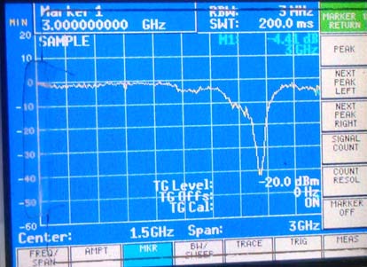
The proposed patch is simulated at 3GHz frequency and we seen that at all the feed points the return loss is below -10bd. At all the feed point we have obtain the bandwidth. This patch is simulated only on 3GHz, but if simulation is done at higher frequency then it may be possible theata wide bandwidth obtain and if this is possible then we can use the proposed antenna at any feed point. From this work we can prove that a single patch antenna can be used at much application.
From second patch it may be possible that feed point location is not changed but results can be improved when we goes toward higher frequency. In future if we design a patch at low frequency and bandwidth is satisfactory for applications then we can also attained satisfactory results at higher frequency at same feed point location .but due to limitations of testing in here we are only simulated results obtained from IE3D.
From last H shape patch we attained a dual bandwidth, we have seen that second band of result is goes below -10db at frequency 2.3GHz to 3 GHz. And this bandwidth can be improved if we simulate same H patch at higher frequency above to 3GHz. The bandwidth of this band can be improve in future, but due to limitations in testing for patch above 3GHz we are goes on above 3GHz.
10. XIII Issue XVI Version

| Feed | 1 | 2 | 3 | 4 |
| points | ||||
| X | 24.575 | 7.75 | 8.525 | 24.875 |
| Y | 35.075 | 35.25 | 5.875 | 5.875 |
| Return | 30 | 51 | 34 | 47 |
| Loss | ||||
| Bandwidth 26.84% | 31.25% | 28.69% | 25% | |
| 4Ghz | 5Ghz | 6Ghz | |
| W g (mm) | 32.856 | 28.205 | 25.104 |
| L g (mm) | 27.404 | 23.686 | 21.197 |
| W e (mm) | 23.256 | 18.605 | 15.504 |
| L e (mm) | 17.804 | 14.085 | 11.597 |
| Specifications | 4GHz | 5GHz | 6GHz |
| X(mm) | 5.425 | 5.375 | 5.225 |
| Y(mm) | 10.625 | 8.65 | 6.5 |
| Band | Single | Single | Dual |
| Band Width (%) | 42.42 | 50 | 4.74 ( 1 st |
| Band) | |||
| 47 (2 nd | |||
| Band) | |||
| Return Loss | -32 | -28 | -19 |
| -20 |
| Antenna | Dimension in |
| Parameters | mm |
| h | 1.6 |
| W g | 40.6 |
| L g | 33.57 |
| W p | 23.8 |
| L p | 23.97 |
| K 1 & K 2 | 8.445 |
| L 1 | 3 |
| W 1 | 3 |
| I 1 | 4.8 |