1. Introduction
he helical antenna has always been in demand for wireless communication and has gone through various kinds modification for gain and bandwidth enhancement techniques [1][2][3][4] to improve the overall antenna performance. Another important feature as discussed in [5][6] which make the helical antenna more demanding is its power handling capacity. But the problem in helical antenna arrived when the helical antenna designs were only limited to WLAN (2.4 GHz) and S-band frequencies. The reason being that existing equations and mathematical proofs given by Kraus [7] and other authors showed that, the stability in helical antenna at much higher frequency is not feasible.
So a demand arises to demonstrate a stable frequency response and impedance matching in helical antenna for higher range of frequencies.
The work presented in this paper aims to show that helical antenna can still be used at higher frequencies even beyond C-band. Also here attention is focused on the enhancement of bandwidth and gain along with the reduction in size of helical antenna which finds important application in communication systems.
The issue of compact size in the antenna design has always been challenging barrier. So to overcome this barrier, a conformal partial cavity has been designed which backs the helical antenna. The
2. Rahul Yadav
Authors :
e-mail: [email protected], name partial cavity is assigned because unlike the actual cavity which has its all side enclosed, the cavity designed here has opening in three different directions. To keep the system more compact, helix turns has been compromised in the design. In this paper, an L-wall partial cavity backed 1½ turn helical antenna is designed and its parameters like gain, bandwidth, radiation pattern and power handling capacity are investigated. In the design, the parameter like spacing between walls is also taken into account to carry out a detail analysis. To make the antenna reconfigurable, the helix is loaded inside the cavity in such a way that it can thus be rotated manually without disturbing the feed. This is done by digging a hole at the center of the ground plane whose diameter is 1mm extra compared to that of diameter of SMA connector. This allows soldering of the helix feed pin and SMA connector together conveniently. The bonding connection is coated with PTFE to prevent it from shorting with the cavity body.
It is important to note that the conventional helical antennas have generally a single resonant mode [8][9]. However in [10], the higher order mode can be realized by modifying the ground plane and geometry of the helical antenna. Although the helical antenna is a three dimensional entity whose modes are characterized by half wave variation along x, y and z axis, for simplicity the modes can be reduced to TM mn by observing the wavelength variation in 'x' and 'y' direction only form the top view.
3. II.
4. Antenna Design & Theory
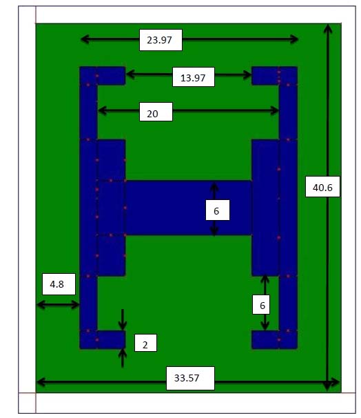
The conventional design of helical antenna explains that to have proper circular polarization of electric fields, the helix should have atleast three turns and for that its circumference (C) should be in between 0.75?-1.33?. However the number of turns can be reduced to 1½ if the electric fields from the antenna can be confined with double the intensity from conventional helix. With the decrease in helical turns, there is possibility that the higher order modes may not be excited but this can be accounted by loading helix inside the cavity. It is important to note that the primary reason for reducing the turns of helix is the fact that it will follow odd symmetry with respect to each of the cavity wall and will prov ide greater degree of variation in the design. The pitch angle of the helix is kept as 14 degree. The rectangular configuration of helical is chosen in order to have non-uniform distribution of current along the antenna which will eventually help to excite higher order modes along with the fundamental mode, whereas in case of conventional cylindrical helix only fundamental mode is excited. So a rectangular helix is designed with a strip width of 2mm and thickness of 1mm as shown in Fig. 1.
5. a) Design of Impedance Matching Cavity
To demonstrate a stable response of helical antenna for higher range frequencies, an L-wall cavity has been designed as shown in Fig. 2a. The design of Lwall shaped partial cavity begins with the assumption that not necessarily the cavity should always enclose the antenna to achieve more directive pattern. Instead, the proper orientation of metallic walls around the helical antenna can significantly help to improve the overall gain and bandwidth of the antenna. So the cavity which is basically a modified ground plane to the helical antenna is designed assuming 13.6GHz ± 1.4GHz as the critical range of frequency. The higher range of frequency is selected to achieve impedance matching of helical with the standard 50? excitation. Also this critical frequency leads to a minimum height of cavity wall with which efficient confinement of electric field is possible. So all the dimensions of cavity calculated here is critical
? = c/f (1)Where 'c' is the velocity of light and 'f' is critical frequency
The designed cavity has a height of 20mm and ground base as (24×24) mm. Now the cavity is actually acting as a resonator whose inductance and capacitance per axial inch can be calculated as; antenna is placed with its feed pin at the center of the cavity from inner dimension. The orientation of helix with respect to the cavity walls is another potential parameter which will help to investigate the behavior of helical antenna in various directions inside the cavity. For this, the antenna is rotated with an offset angle of 45 o in anticlockwise direction and thereby making the design reconfigurable in nature. Figure 3 shows the top view of helix rotation inside the L-wall partial cavity.
6. III.
7. Result Analysis & Discussion
The simulation is performed in CST Microwave Studio Suite using time domain solver with accuracy set to -40dB. The boundary condition which plays an important role in the numerical analysis is kept as open space around the antenna. To investigate the effect of cavity and its corresponding enhancement in gain and bandwidth of helical antenna, initially a helix is simulated without the use of L-wall cavity so that a better comparative analysis can be made.
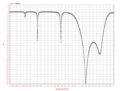
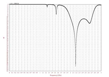
The analysis begins with the simulation of helical antenna only with a rectangular ground plane of (24×24) mm. Figure 4 shows the plot of reflection coefficient (S 11 ) in the frequency range of 5-15 GHz. It is observed that since the turns are too low, the result of S 11 is not below -10dB. From Fig. 5, it explains that theVSWR (voltage standing wave ratio) is not below 2 indicating that there is no impedance matching in helical antenna for higherrange of frequencies and the resonant modes are too weak. However these can be improved by loading the designed 1½ turn helical antenna in a specially design cavity.
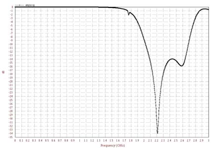
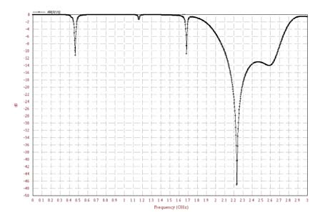
The plots of reflection coefficient for L-wall cavity backed helical antenna at various rotation angles is shown in Fig. 6. It is observed that at 0 o position,a dual band is obtained from 7.3-8.4GHz and 13.49-15GHz with a bandwidth of 2.68GHz. This is the highest simulated bandwidth of helical antenna in this design because the spacing between helix and wall is less which results in more reflection of electric fields from the walls and also the helix end is pointing towards the corner of the L-wall. So the bandwidth should be higher at 45 o position also, but this is not the case here because at 45 o position the helix end starts orienting slightly outward from the L-wall. Therefore at 45 o position instead of dual band only single band is resonated.Also it is noted that from 0 o to 135 o position, the bandwidth is eventually decreasing and dual band is only occurring at 0 o and 90 o position.At 90 o position the helix end is outward the wall, but in 0 o position the helix end is inwards the L-section of the wall, so the bandwidth at 0 o position is high as compared to 90 o position.Rest of the angles is with single frequency band only. Beyond 180 o the bandwidth start increasing up to 270 o , this is because the spacing of the helix from the cavity wall is decreasing.
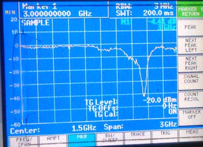
It is observed that if the helix approaches closer to the walls, the bandwidth increases which can be seen in Table .1. At 135 o the spacing between the helix and the base of L-wall is more, so the bandwidth is poor i.e. 0.41GHz only. After the comparative analysis made for simulated and measured results of cavity backed helix, it is seen that there is an agreement in comparison made for majority of the helix rotation angle. However at positions like 90 0 , 180 0 and 225 0 , a slight shift and increase in the measured bandwidth is noticed. A detail explanation for this is illustrated in section IV.
The radiation pattern as shown in Fig. 7 is simulated for each of the helix position inside the cavity at peak resonance for the respective orientations in Eplane. It is observed that due to the manual reconfiguration of helix orientation, both omnidirectional and directive nature of pattern is obtained which makes the antenna suitable for point to point and point to multipoint communication. Next, to find the maximum power handling capacity of antenna, the intensity of near electric field vector is solved which is founds to be 7837 V/m as shown in Fig. 9. Now assuming that breakdown threshold for helical antenna which is made of copper as 50 MV/m [11], the maximum power handling capacity comes out to be 40.67 MW.
8. Experimental Observations
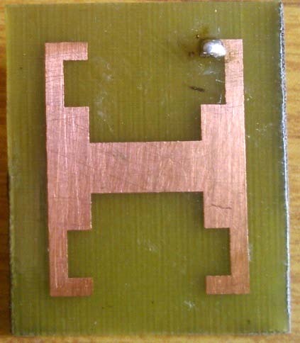
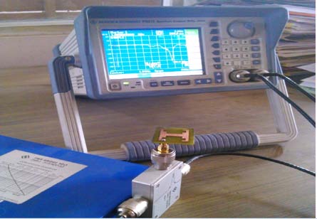
In the fabricated design of cavity backed helical antenna, the helix which is made using copper and the impedance matching L-wall cavity which is fabricated using aluminum metal as shown in Fig. 2b, it is found that the joint connection between the helix and feed pin plays an important in the distribution of current along the helical antenna. In the modeling of antenna in Computer Simulation Tool (CST), the joint connection between the helix and feed pin is abrupt however this has been improved in the practical implementation of helix as shown in Fig. 10. The geometrical operation of lofting has been employed to enhance the flow of current from the feed along the helix. The lofting certainly improves the current distribution along the antenna and thereby increases the overall bandwidth of the antenna. The measured results of reflection coefficient show improvement in bandwidth over the simulated results at some of the rotation angles.
9. Conclusion
A compact and conformal helical antenna design has been demonstrated with a stable frequency response. It is found that modification of ground plane which is the L-wall cavity here in the design plays an important in confinement of near field electric vector. Also the orientation of helix inside the cavity should be appropriately adjusted to provide a multiple reflectionsof

| Helix | No. of | Resonant Bands(GHz) Bandwidth | |
| Position | Bands | (GHz) | |
| 0 0 | Dual | 7.3-8.44 & 13.49-15 | 2.68 |
| 45 0 | Single | 9.58-11.91 | 2.33 |
| 90 0 | Dual | 7.21-7.93 & 13.42-13.93 | 1.22 |
| 135 0 | Single | 13.5-14.44 | 0.94 |
| 180 0 | Single | 13.15-14.33 | 1.18 |
| 225 0 | Single | 13.44-14.82 | 1.38 |
| 270 0 | Single | 3.49-15.03 | 1.54 |
| 315 0 | Single | 6.18-6.59 | 0.41 |
| Helix Position Peak Gain(dB) | |
| 0 0 | 11.28 |
| 45 0 | 11.2 |
| 90 0 | 10.7 |
| 135 0 | 9.7 |
| 180 0 | 10 |
| 225 0 | 8.8 |
| 270 0 | 8.2 |
| 315 0 | 10.7 |