1. Design and Implementation of Internet based Power Monitoring and Controlling System using PIC16F84A Microcontroller for Energy Regulation
Vinyl Ho Oquino Abstract-One of the major causes of high electrical energy consumption is unawareness of usage of electricity. Most people forget of turning-off lights and electrical equipment when not used or even when they are not around. Study shows that 80 per cent of the employee in different offices would forget to turn off lights and other electrical equipment when they are out of the office. The internet based remote control systems are commonly available in most advanced countries. Thus, for developing country like Ethiopia this technology is very much helpful for regulating the energy consumption of every government and private establishment.
The main objective of this project is to control and monitor any electrical appliances using internet anywhere. The main components of this project were low cost computer as server and a low cost microcontroller PIC16F84A. The microcontroller module was develop and connected to the server computer.
The server computer was connected to the internet in order to be accessible anywhere. The microcontroller controls and monitors the status of the connected appliances. The web application was developed using HTML and PHP scripting language. The hardware and software of the system were tested in one of the universities in Ethiopia and one College School in Philippines. As a result the system works efficiently and effectively in the both university and college school. The system is now currently implemented in the Philippines.
2. Introduction
nergy usage depends on the time and power rating of the loads. Monitoring to the different facilities helps the administrator or owner manage the energy consumption of the building. Aside from energy management, the safety, maintenance, and reliability of the facilities are being maintained. [1] Many commercially made power monitoring products are available in the market today. [2] But some of these products are costly and not serviceable. This results to a high maintenance cost by using this product.
This study aimed to design and implement an internet based system that can monitor and control the electrical power using a low cost microcontroller. The system is accessible using the internet and the server computer. The output of study can benefit the commercial establishment buildings, universities and residential establishments that need to monitor and control the electricity of the facilities.
3. II.
4. Hardware Design
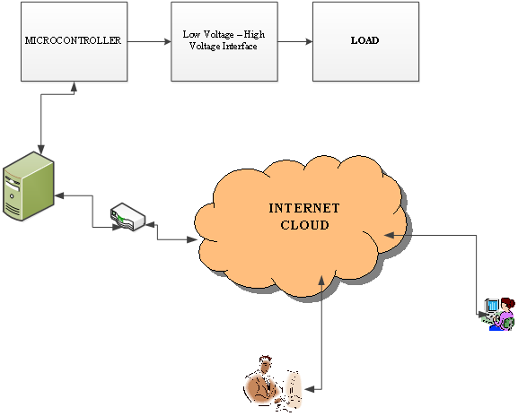
The hardware component of the research project includes the microcontroller module, the low voltage to high voltage interface driver, the computer server, and the modem router for the internet connectivity. The block diagram and the connection to the internet were shown in figure 1. The outputs of the microcontroller were connected to the low voltage -high voltage interface. The low voltage -high voltage interface control the load based on the output of the microcontroller. The microcontroller was also connected to the server computer via a serial communication. The server computer was connected to the modem router in order to access via internet. The database application was installed in the server computer recording all the status of the loads. Any activities by the microcontroller were stored in the database through the server computer.
5. a) Microcontroller Circuit Design
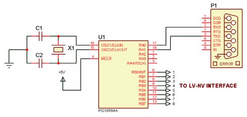
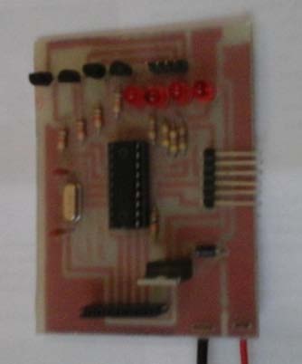
The PIC16F84A microcontroller was used to control the load through the low voltage -high voltage interface. The port B of microcontroller was used as output. Figure 2 shows the connection of the microcontroller and the serial port. The 4 MHz crystal oscillator was used in the controller circuit as the clock speed of the microcontroller. A 22 pF ceramic capacitor was also used as filter connected to the oscillator pin of the microcontroller. The port A of microcontroller was used as serial port. This port was used to communicate with the computer server.
6. b) The Low voltage -High voltage Interface
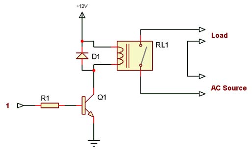
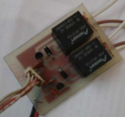
The output of the microcontroller was only 5V DC. The loads operate at 240V AC. The low voltagehigh voltage interface was used to connect the microcontroller to the loads. The interface connection was shown in figure 3. Thus, the value of resistor was 4.3 ohms.
7. c) The Power Supply
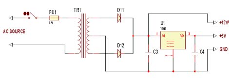
The microcontroller operates at 5V DC supply. The relay operates at 12V DC. The power supply circuit for the study was shown in figure 4. The power supply uses a full wave rectifier circuit to convert the ac voltages to dc voltages. The 2200uF capacitor was used in the circuit as filter capacitor to minimize the ripple. A LM7805 regulator was used to provide a 5V output voltage for microcontroller.
8. Software Developments
Different software was used in the research. Each of this software has its own functionality in communicating the hardware.
9. a) Embedded Software
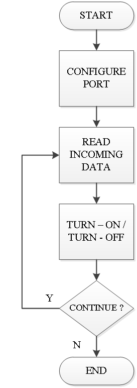
The microcontroller needs embedded program instruction in order to give an output based on the requirement. Figure 5 shows the flow chart diagram of the embedded program. The program was written using mikro C compiler and compile directly to hex file. The PIC16F84A microcontroller doesn't have built-in serial port module. The software UART library was used to configure PORTA to communicate serially.
[3] After configuring the different port used in the system, the microcontroller starts reading the incoming data via serial port. The data sent to serial port was used either to turn-on or turn-off the load. Then after the execution of turning-on or off, the program decide either to continue or end the program. This program continues as long as the microcontroller receives power.
10. b) Controller Software
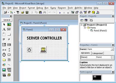
The controller software was written in visual basic. It was used to send and receive data to microcontroller. Figure 6 shows the controller program written in visual basic.
11. Figure 6 : The Controller Program in Visual Basic
The visual basic has communication tool that was used to communicate with the serial port. The timer tool was used in order to continue sending and receiving data with the microcontroller. The visual basic program also communicate the MySQL database for updating the data.
12. c) Web Application
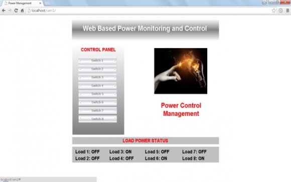
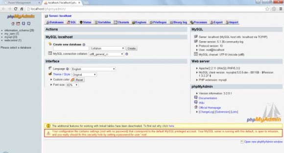
A web page application was written using HTML and PHP scripting. The MySQL database was also used to store the status of the load. Figure 7 shows the web page application for monitoring the load power status. Using the webpage, the users can turn-on and turn-off the power. The PHP scripting language was used to communicate the serial port and store the data into the database. The HTML was used for the display in the web page. Figure 8 shows the control panel of MySQL database. The database was created using the PHP admin cpanel interface.
13. Network and Server Configurations
The server computer was connected to the router in order to be connected to the internet. The user access the internet to the computer via router connected in the system.
14. a) Server Computer Configuration
The server computer contains all necessary software application needed for the system. The server computer contains the WAMP web server and the Year 2016 ( ) controller software written in visual basic. The WAMP server application software was installed to host the webpages for the system. The controller software that was written in visual basic was used to communicate the server computer and the microcontroller via USB port.
The microcontroller received data from computer through serial communication.
15. b) Router Configuration
All hardware connected to internet has its own ID or address. The router was used to select the data path based on the address of the data. In order to connect to the internet a public IP address was issued by the internet provider. [4] All connected to the router can access the internet. If the computer wants to broadcast its data to the internet, the router was configured its port forward. [5] The port forwarding option of the router needs to be enabled. Assign a port number corresponding to the IP address of the computer connected to the router. There were different procedures of configuring router depending on the manufacturer.
V.
16. Implementation Results
The final output of the development of low cost power monitoring and controlling system is discussed in this section.
The microcontroller module development was shown in figure 9. The PIC16F84A microcontroller was used in the module. It was designed to communicate form the load to the computer. The embedded program that was loaded to the microcontroller uses soft UART library. This library was used so that it can be configured by using serial communication.
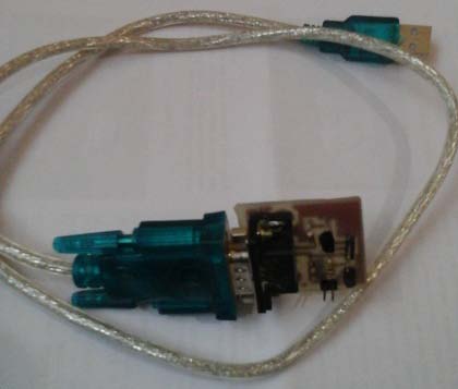
The serial communication was used to communicate with the server computer. The USB to RS232 converter was used in order to connect the microcontroller with the computer. Figure 11 shows the USB to RS232 converter cable. This cable was used since the computer uses USB port. The interface module with the relay was directly connected in the circuit breaker in the panel board as shown in figure 12. The relay contactor was used to control the power from each load connected to the circuit breaker. The circuit breaker was used to protect the system against short circuit and over loading form the load side. And it was a successfully adopted by the administrator. The said project was applicable in any buildings that required power monitoring and controlling for energy regulation. The system were tested 24/7 without