1. I. INTRODUCTION
n modern VLSI system, power dissipation is very high due to rapid switching of internal signals. Landauer showed that the circuits designed using irreversible elements dissipate heat due to the loss of information bits [1]. It is proved that the loss of every bit of information results in dissipation of KT*log2 Joule of heat energy where K is the Boltzmann constant and T is the temperature at which the operation is performed.
Bennett showed that this heat dissipation due to information loss can be avoided if the circuit is designed using reversible logic gates [1]. A gate is considered to be reversible only if each and every input has a unique output assignment. Hence there is a one to one mapping between the input and output vectors. A reversible logic gate has same number of inputs and outputs.
2. II.
3. BASIC REVERSIBLE GATES
There exist many reversible gates in the literature. Among them 2*2 Feynman gate, 3*3 Fredkin gate, 3*3 Toffoli gate and 3*3 Peres gate are the most referred. The detailed cost of a reversible gate depends on any particular realization of quantum logic [2]. Generally, the cost is calculated as a total sum of 2*2 quantum primitives used. The cost of Toffoli gate is exactly the same as the cost of Fredkin gate and is 5. The only cheapest quantum realization of a complete (universal) 3*3 reversible gate is Peres gate and its cost is 4.
I3 I2 I1 I0 Operation 0 0 0 0 Clear 0 0 0 1 A+B 0 0 1 0 A-B 0 0 1 1 A*B 0 1 0 0 A++ 0 1 0 1 A-- 0 1 1 0 Left Shift 0 1 1 1 Right Shift 1 0 0 0 Or 1 0 0 1 And 1 0 1 0 Not 1 0 1 1 Xor 1 1 0 0 Nor 1 1 0 1 Nand 1 1 1 0 Xnor 1 1 1 1 PresetThe 8-bit reversible adder/subtractor has been designed using Peres gates and Feynman gates [3]. HNG gates and Peres gates are used in the design of the 8-bit reversible multiplier [6].The left and right shifter blocks are designed using reversible multiplexers.
4. b) Register File
The register file includes 16 registers and two 4 to 16 decoders as shown in the Figure .6. The two select signals 'load' and 'enable' are used for loading data into and reading value of data from the individual registers of the register file respectively. The 4 to 16 decoder is designed using reversible Fredkin gates [4]. ? ALU result registers are also controlled buffer register used to store the result of the ALU operation. ? The Data Bus Buffer is another controlled buffer register that takes input from memory module. It is directly connected to the data bus.
IV.
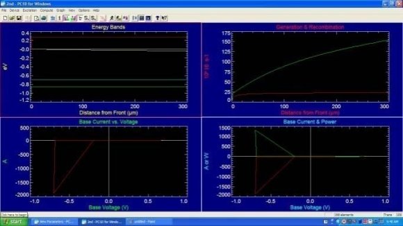
5. SIMULATION RESULTS
All the blocks are modelled using VERILOG. The functional verification of the codes is analysed using ModelSim-Altera 6.4a (Quartus II 9.0) Starter Edition and synthesised using Xilinx ISE Design Suite 13. reversible 8-bit processor has been proposed. Each block of the processor was designed using the basic reversible gates.
In future, this design can be extended to any number of bits. This paper provides the circuit level implementation of the reversible processor. Further this design may be extended to transistor implementation which would help in easier analysis of power.

![Figure 7 : Instruction Format The important block of the control unit is the instruction decoder, which controls the eight memory components of the processor. Instruction decoder consists of two 3 to 8 decoders as shown in Figure.8. Two select signals 'load' and 'enable' are used for the decoders. The 3 to 8 decoder is designed using reversible Fredkin gates [4].](https://engineeringresearch.org/index.php/GJRE/article/download/860/version/100357/2-Design-of-Bit-Arithmetic-Processor-Unit_html/7558/image-8.png)
| Device Id | Device Name |
| 000 | Accumulator Register |
| 001 | ALU Result Registers |
| 010 | Data Bus Buffer Register |