1. Introduction
C-DC converters are widely used in various applications. These converters are usually operated in two modes of operation, namely continuous and discontinuous conduction modes [1]. The discontinuous conduction mode of operation of the converter is most frequently used for light load applications. It is also useful for extracting maximum power efficiently from the solar panel [2,3].
Due to various applications and needs of dc-dc converter operating in DCM, it is very essential to have a proper analytical model for this mode of operation for the analysis and design. The literature shows that more effort has been taken in this view for past three decades [2,4].
One of the most widely used techniques in the design procedure in power electronics is averaging technique. This technique provides the basic analytical foundation for the most power electronic design. In fact classical averaging procedure is not suitable when there are state discontinuities. At high switching operations the periodic solution has some amplitude ripple, and these ripples are not considered in the classical averaging theory. Due to this it has been found that the directly obtained averaged models are inaccurate for the converters operated in DCM [4]. This has inculcated to take efforts to obtain more accurate averaging method.
In the continuous-time averaging procedure, each circuit topology is modeled separately and then combined in on approximated model [4,5]. The duty cycle is a discrete-time variable, but treated as a continuous time variable in the existing continuous-time averaged models. Thus the orbital nature of the periodic solution is not obtained. Intern the periodic solution of the converters is averaged to equilibrium to form a nominal solution. In contrast, no such approximations are made in the sample date model. This provides the most accurate result, which replicates the actual behavior of PWM systems and is also suitable for digital control process. Sampled-data models allow us to focus on cycle -to-cycle behavior, ignoring intra cycle ripples. This makes them effective in general simulation, analysis and design. These models predict the values of signals at the beginning of each switching period, which most of the times represent peaks or valleys of the signals rather than average values. To better understand the average behavior of the system, a discrete-time model for the OCA signals was presented in [6].
In this paper, a sampled-data model for nonideal closed loop PWM converters operating in DCM is formulated. This gives the exact discrete-time mathematical representation of the values of the output and internal signals at constant frequency. A discretetime model to provide the one-cycle-average (OCA) signals of the non ideal closed loop PWM converters operating in DCM is proposed. This model provides the exact discrete-time mathematical representation of the averaged values of the output signal at each switching period. It also provides the average values of other internal signals with little increase in simulation time. The main motivation for the new model is based on the fact that, in many power electronic applications, it is the average values of the voltage and current rather than their instantaneous values that are of greatest interest. In addition to that, the existing models are II.
2. Existing Average Models
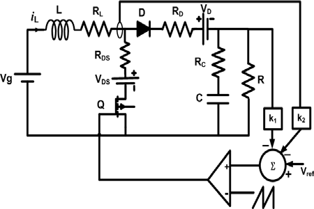
The modeling method is validated by a nonideal boost converter with feedback as shown in Figure 1 for the different existing averaging methods and presented in this section. is the input vector, x(t) R n is the state vector, y(t) R p is the output vector while denotes the length of a switching cycle. Then the DCM PWM converter can be described as [7].
The problem with the state-space averaging approach in DCM is that we are averaging just the matrix parameters, and not necessarily the state variable themselves. It is intended that (3) will apply when the true average of each state variable is used, but the average inductor current depends on the parameters and duty ratios. Considering this, the modified statespace averaged model that would correctly predict the behavior in DCM for the boost converter is given as [2].
Where M is the modification Matrix and its given by (6) Based on ( 4), ( 5) and ( 6) the averaged model can also be derived considering non-ideality in the switching stage components, and is given by
?(t) = ? ? ? A 1 x(t) + B 1 u(t) ; t ? ? 1 A 2 x(t) + B 2 u(t) ; t ? ? 2 A 3 x(t) + B 3 u(t) ; t ? ? 3 y(t) = ? ? ? C 1 x(t) , t ? ? 1 C 2 x(t) , t ? ? 2 C 3 x(t) , t ? ? 3 ?(t) = [d 1 A 1 + d 2 A 2 + (1 ? d 1 ? d 2 )A 3 ]M x(t) +[d 1 B 1 + d 2 B 2 + (1 ? d 1 ? d 2 )B 3 ]u(t) M = ? ? 1 d1+d2 0 0 1 ? ? d 2 = 2Li L d 1 T s V g ? d 1 di L dt = (R L + R D S )(R + R C )(V g d 2 1 T s ) 2L 2 (R + R C ) ? ((R L + R D )(R + R C ) + RR C )(2i C L ? d 2 1 V g T s ) 2L 2 (R + R C ) ? (2i L L ? d 2 1 V g T s )RV C LV g d 1 T s (R + R C ) + dv C dt = 1 C(R + R C ) Ri L ? V C ? d 2 1 V g T s R 2L c) Conventional Discrete-Time ModelThe conventional discrete-time mode (CDTM) is given by [4] (7)
x k+1 = A(d 1 k , d 2 k )x k + B(d 1 k , d 2 k )u k(1)(2) (4)
(5)
XIII Issue V Version I 10 ( )
YearWhere the input nonlinearities A(d 1 , d 2 ) and B(d 1 , d 2 ) are given by
A(d 1 , d 2 ) := ? 3 ? 2 ? 1 B(d 1 , d 2 ) := ? 3 (? 2 Î?" 1 + Î?" 2 ) + Î?" 3 (8)(9)The arguments d 1 T s , d 2 T s , and
(1?d 1 ?d 2 )T s for (? 1 ,? 2 , ? 3 , Î?" 1 , Î?" 2 and Î?" 3 ), respectively are omitted from the above equations for notation simplicity. Where
u(t) ? R m ? ? T s 2i L LV g ? d 2 1 V D S V g T s ? 2i L LV D + d 2 1 V g V D T s LV g d 1 T sWhere The system switches between three topologies (A 1, B 1 ,C 1 ), (A 2 ,B 2 ,C 2 ), and (A 3 ,B 3 ,C 3 ) , with switching intervals determined by Where (d 1 k +d 2 k ) [0, 1] are the switch duty ratios, and k is the discrete-time index. All auxiliary inputs will be assumed to be piecewise constants, i.e. for all t ). This assumption is not necessary and is made for convenience only; more general cases would only require more complex notations. This is the exact switching model which will be used as the base model for comparison of different methods. The control scheme given in is applied, where is , and in [8].
b) DCM State-Space Average Model (SSA)
In the conventional state-space averaging method the averaged model for DCM has been presented previously in numerous publications [2]. The converters state-space equation in this mode is given by
? 1 := kT s ? t < kT s + d 1 k T s ? 2 := kT s + d 1 k T s ? t < kT s + (d 1 k + d 2 k )T s ? 3 := kT s + (d 1 k + d 2 k )T s ? t < kT s + T s ? kT ( + 1)T k s s [ m( t) = V ref ? k 1 i( t) ? k 2 v( t) V ref = 0.13, k 1 = 0.174, k 2 = ?0 0435 as ?(t) = [d 1 A 1 + d 2 A 2 + (1 ? d 1 ? d 2 )A 3 ]x(t) +[d 1 B 1 + d 2 B 2 + (1 ? d 1 ? d 2 )B 3 ]u(t)(3)?
u(t) = u kWhere d 1 and d 2 are the duty ratios and d 2 can be determined as follows Note that the averaging operation adds "sensor" dynamics to the system; as a consequence, the largesignal model ( 11
? * i (t) := 1 T s t 0 ? i (? )d? Î?" * i (t) := 1 T s t 0 Î?" i (? )d?. x * ? R n p + x * k+1 := x k+1 C(d 1 k , d 2 k )x k + D(d 1 k , d 2 k )u k x * k+1 = A * (d 1 k , d 2 k )x * k + B * (d 1 k , d 2 k )u k y * k = C * x * k A * (d 1 , d 2 ) := B * (d 1 , d 2 ) := B(d 1 , d 2 ) D(d 1 , d 2 ) C * (d 1 , d 2 ) := 0 p×n I p×pNote that not only the OCA values of output signal will be available but also the values of the signals (without averaging) at the beginning of every switching period as well.
3. b) Feedback Computation
The modulation signal for feedback control is
m(t) = V ref ? k 1 i(t) ? k 2 v(t)=and the duty ratio at each switching period is . The time instant t* at which the modulation signal crosses 16)
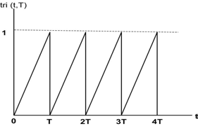
tri(t * , T s ) = V ref ? s + t * ) = V ref ? K{? 1 (t * )x k + Î?" 1 (t * )u k }at each time instant , where the sawtooth function is shown in Figure 2 and mathematically represented by tri
A(d 1 , d 2 ) 0 n×p C(d 1 , d 2 ) 0 p×p V ref ?Kx(t) t * Ts k III.4. Proposed Model
This section introduces the new averaged discrete-time model for closed loop PWM dc-dc converter operating in DCM considering conduction losses. Description of the original system and derivation of the proposed model are discussed here. The onecycle average (OCA) representation of the output signal [6] is given by (10)
The signal,
) is used to develop a new discrete-time model for PWM converters operating in DCM. This model provides the basis for discrete-time simulation of the averaged value of any state in the DCM PWM system, even during transient non-periodic operating conditions. a) Proposed OCA Discrete-Time Model It is desired to compute, without approximation, the evolution of all system variables at the sampling instants, assuming three different topologies for the system. Since the state and output equations ( 1 , and
x k+1 = A(d 1 k , d 2 k )x k + B(d 1 k , d 2 k )u k y * k+1 = C(d 1 k , d 2 k )x k + D(d 1 k , d 2 k )u k A(d 1 , d 2 ) := ? 3 ? 2 ? 1 B(d 1 , d 2 ) := ? 3 (? 2 Î?" 1 + Î?" 2 ) + Î?" 3 C(d 1 , d 2 ) := C 1 ? * 1 + C 2 ? * 2 ? 1 + C 3 ? * 3 ? 2 ? 1 D(d 1 , d 2 ) := C 1 Î?" * 1 + C 2 (? * 2 Î?" 1 + Î?" * 2 ) +C 3 (? * 3 (? 2 Î?" 1 + Î?" 2 ) + Î?" * 3 ) ? i (t) := e Ait Î?" i((1?d 1 ?d 2 ) T s ? ( 1 1 , Î?" * 3 )floor For reasonably high switching frequency, the value of x(kT + t*) can be approximated by neglecting the higher order terms in the Taylor expansion of the nonlinear functions ? 1 and Î?" 1 . That is And hence, a good approximation of ( 16) becomes
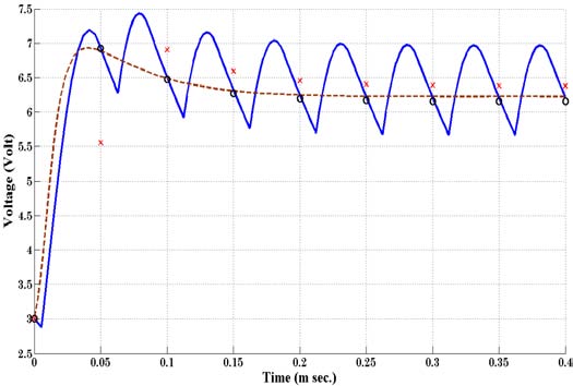
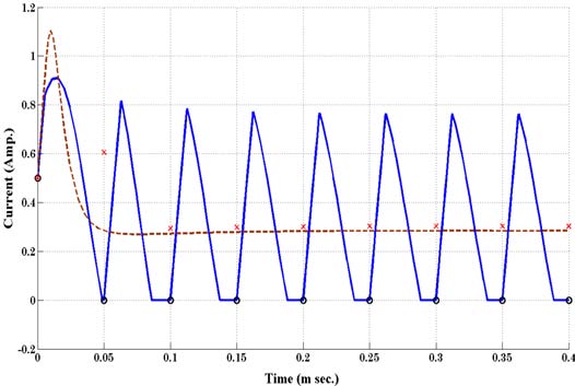
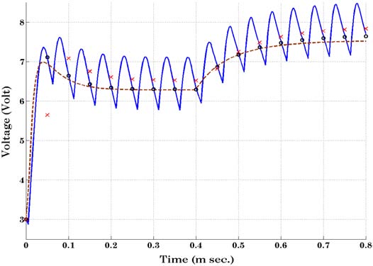
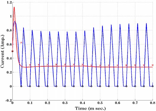
5. Numerical Example
To compare existing models with DCM OCA model, consider a Boost converter with feedback considering conduction loss shown in Figure 1. The
? 1 (t * ) = I + A 1 t * + A 2 1 2! t * 2 + . . . ? I + A 1 t * Î?" 1 (t * ) = (It * + A 1 t * 2 2! + . . .)B 1 ? It * B 1 tri(t * , T s ) ? V ref ? K{(I + A 1 t * )x k + B 1 t * u k } tri(t * , T s ) equals to t Ts for t * ? (kT s , (k + ], 1)T s t * T s ? V ref ? K{(I + A 1 t * )x k + B 1 t * u k } d k = t * T s ? V ref ? Kx k KT s (A 1 x k + B 1 u k ) + 1 input is u = V gR L = 0.0176 ?, R C = 30 m?, A 1 = ? ? ? (R L +R D S ) L 0 0 ? 1 (R+R C )C ? ? ; A 2 = ? ? ? ? (R L +R D )(R+R C )+RR C L(R+R C ) ? R L(R+R C ) R C(R+R C ) ? 1 C(R+R C ) ? ? ? ; t, T s ) = tTs ? ( t Ts ). x
1 = i L x 2 = v C .T s = 50 ?s.
R DS = 0.17 ?, R D = 0.15 ?, V DS = 0.17 V,
V D =0.4 V are periodically A 3 = ? ? ? (R L +R D S ) L 0 0 ? 1 (R+R C )C ? ? ; B 1 = ? ? 1 L ? 1 L 0 0 0 0 ? ? ; B 2 = ? ? 1 L 0 ? 1
| ) -(12) is not in standard | ||||
| statespace form. By defining the augmented state | ||||
| vector | such that | |||
| (13) | ||||
| An | equivalent | (but | standard | form) |
| representation of the OCA large-signal model is | ||||
| given by: | ||||
| (14) | ||||
| (15) | ||||
| Where | ||||
| © 2013 Global Journals Inc. (US) | ||||