1. Introduction
teel wires are used in civil engineering as presstressing steel wires and as suspension and/or cable-stayed bridge wires. They are also used as tensile armour wires which provide tensile and hoop reinforcement to flexible pipes that are used for offshore oil and gas transportation. The fracture performance (prediction of fracture load/stress, fracture strain/ displacement at fracture, fracture initiation point, fracture propagation and fracture path or sequence) of steel wires is a major concern in civil engineering construction and maintenance of civil engineering structures where wires provide the required structural reinforcement (Toribio and Ayaso, 2003). Recent research on the failure analysis of wires, such as the research conducted by Mahmoud, (2007) on bridge cable wires, and by Valiente, (2004 and2006) on concrete prestressing wires were based on experimental classical fracture mechanics approach using non-standardised fracture mechanics specimens. Non-standardised fracture mechanics specimens were used because the pre-stressing and suspended bridge wires are not large enough for standard traditional fracture mechanics test specimens to be manufactured from the wires [(Mahmoud, 2007); Valiente, (2004 and2006)]. The large specimen size requirement by the traditional classical fracture mechanics approach and the concern about the applicability of the traditional fracture mechanics in civil structures has necessitated the need to employ approaches that explicitly simulate micromechanical material processes which characterises fracture in civil structures (Fell and Kanvinde, 2009).
Micromechanics-based (micromechanical and phenomenological) fracture mechanics models serve as alternatives to the traditional classical fracture mechanics when standard fracture mechanics specimens cannot be obtained and when a safe use of the classical fracture mechanics concepts cannot be insured (Pardoen et al, 2010). Micromechanics fracture approach guarantees the transferability from specimens to structures over a wide range of sizes and geometries and is suitable for problems involving ductile fracture of crack-free bodies as it does not require the pre-cracked specimen needed for classical fracture mechanics tests (Bernauer and Brocks, 2002).
Micromechanical fracture modeling involves the modelling of void nucleation and growth, and is based on the assumption that ductile fracture occurs when the void volume fraction reaches a critical level; hence, such models involve modelling of void nucleation and growth (Dunand and Mohr, 2010). Phenomenological models are alternatives to micromechanical based models as they predict ductile fracture without modelling void nucleation and growth (Dunand and Mohr, 2010). Phenomenological models are based on the assumption that ductile fracture occurs when a weighted measure of the accumulated plastic strain, such as the equivalent plastic strain, reaches a critical value (Dunand and Mohr, 2010). The determination of some parameters for micromechanical fracture modelling can be done through metallurgical observations, while others require extensive and expensive material testing (Bernauer and Brocks, 2002).
The parameters needed for phenomenological failure simulation, such as the modeling parameters for the shear and ductile failure simulations can be obtained experimentally. However, obtaining these parameters through direct experimentation may be difficult because it would require experiments over a range of stress triaxiality for the ductile failure simulation, and requires experiments over a range of shear stress ratio for shear failure simulation (Simulia, 2007). Consequently, the determination of the damage and failure parameters remains predominantly a phenomenological fitting procedure which requires a combination of testing and numerical simulations (Bernauer and Brocks, 2002). The phenomenological fitting procedure involves keeping some parameters constant and varying others during numerical simulations until the simulation results fit the experimental data, usually up to the fracture initiation point, which is marked by a sudden drop of load. The fracture initiation point represents the onset of macroscopic fracture at which void coalescence is "supposed" to start (Bernauer and Brocks, 2002). The values of the set of damage and fracture parameters at which the numerical data fits with the experimental data at the onset of macroscopic fracture has become a common technique to determine the critical fracture parameters (Bernauer and Brocks, 2002).
There are many micromechanical and phenomenological constitutive models for ductile damage and fracture prediction. However, choosing from the numerous micromechanical and phenomenological models, and identifying their applicability and reliability remains an issue that still needs to be addressed in greater depth (Li et al, 2011). This is because using an inappropriate model may result in unreliable or inappropriate ductile fracture predictions, which has been a problematic issue in industrial applications of ductile failure models (Li et al, 2011). Also the need to identify the ductile fracture model which is able to predict ductile fracture in a way that is to the largest extent in agreement with actual phenomena in a material has been stressed by (Rakin et al, 2004). However, in most published literature such as Bernauer and Brocks, (2002); Dunand and Mohr, (2010); Li et al, (2011) and Rakin et al, (2004), the appropriateness (applicability and reliability) of many ductile fracture models to describe the fracture behaviour of materials are based on the ability of such models to predict forcedisplacement/reduction in area curves that agree with the experimental curve up to the fracture initiation point. The simulation techniques employed to obtain such curves have also been adjudged to be appropriate without any consideration for the ability of the models to predict the actual fracture shape(s) (actual phenomena) exhibited by the materials/components/specimens.
In this work, the identification of the appropriate ductile fracture model for a typical high strength steel wires used in civil and structural engineering applications from three micromechanics-based models (two phenomenological fracture models: shear and ductile fracture models; and Gurson-Tvergaard-Needleman's micromechanical model) that are inbuilt in Abaqus 6.9-1 finite element (FE) code was conducted by comparing the force-displacement curves and the fracture shapes obtained from experimental tensile testing and finite element (FE) tensile testing simulations. The simulations with the three micromechanics-based fracture models were conducted with the isotropic elastic-plasticity model in-built in Abaqus 6.9-1 finite element code. Details of the isotropic elasticplasticity model and the three micromechanics-based fracture models are presented in the following sections.
2. a) Isotropic elastic-plasticity model
The isotropic elastic-plasticity model in Abaqus is based on linear isotropic elasticity theory and a uniaxial-stress, plastic-strain strain-rate relationship (Simulia, 2007). The elastic aspect of the model is defined in terms of its volumetric and deviatoric components given in equations 1 and 2 respectively obtained from Simulia, (2007). The model is based on a von Mises yield surface with the yield function, , given in equation 3 and a flow rule given in equation 4 obtained from Simulia, (2007).
vol K p (1) el Ge S 2 (2) S S q f : 2 3 (3) n e d de pl pl (4)Where p is the hydrostatic pressure, vol is the volume strain, is the deviatoric stress
3. S q b) Shear Failure Model
The shear failure criterion is a phenomenological model for predicting the onset of damage due to shear bands. Applied stress causes shear band formation and localisation, leading to the formation of cracks within the shear bands and eventual failure (Hooputra et al, (2004). The shear model assumes that the equivalent fracture strain is a function of the variable given in equation 5 obtained from Hooputra et al, (2004).
s k 1 (5)Where S k is a material parameter, is the stress triaxiality and is the ration of the maximum shear stress and the equivalent stress (von Mises) as given in equation 6 obtained from Hooputra et al, (2004).
eq max (6)The equivalent plastic strain for shear fracture with respect to is given in equation 7 obtained from Hooputra et al, (2004). (7) c) Ductile damage and fracture criterion The ductile damage criterion is a phenomenological model for predicting the onset of damage by micro-void nucleation, void growth and void coalescence. Micro-void nucleation could be as a result of micro-cracking of particles and/or fracture or decohesion of second phase inclusions. Plastic straining causes the nucleated voids to grow or enlarge, leading to localisation of plastic flow between the enlarged voids and eventual ductile tearing of the ligaments between the enlarged voids [14]. The ductile failure model assumes that the equivalent fracture strain * * eq given in equation 8 is a function of stress triaxiality
) ( sinh ) ( sinh ) ( sinh * * f f f S S eq) ( sinh ) ( sinh ) ( sinh * * c c c T T eq (8)Where T and T are the equivalent plastic strain in equibiaxial tension/compression at ductile fracture, and and are the stress triaxiality in equibiaxial tension / compression at ductile fracture and is a material parameter.
4. d) Porous metal plasticity
The porous metal plasticity (PMP) model is a micromechanical model used in modelling damage and failure of voided metals. It is based on the Gurson's porous metal plasticity theory which is based on the assumption that the yield stress of the fully dense matrix material is a function of the equivalent plastic strain in the matrix. It predicts failure by nucleation of new voids, and growth and coalescence of both existing voids and nucleated voids, with final failure occurring by ductile crack propagation (ductile tearing). The Gurson's porous metal plasticity model yield condition modified by Tvergaard, (1981) is given in equation 10. where: , leading to the removal of the elements (Tvergaard, 1981).
) ( * c c F c F c f f f f f f f f if F c f f f (10) (11)(12)3 3 2 1 1 q q q q f F c f Critical5. II.
6. Experimental
The details of the experimental measurements and FE simulations are presented in this section.
7. b) Finite element tensile testing simulation
The three dimensional FE simulation of the tensile testing of the wire specimens was conducted using the in-built isotropic elastic-plastic model combined with the ductile, shear and porous metal plasticity fracture models in Abaqus 6.9-1 finite element code. The FE simulation was conducted by fixing the left hand end of the full three dimensional model of the wire and subjecting the right hand end, which is free to move only in the direction of the tensile load to a longitudinal displacement as shown in Figure 1. The FE tensile testing simulation was conducted for the 12mm x 5mm and 12mm x 7mm wire sizes. The outer regions of the model of the wires specimen were meshed with 1mmx1mmx1mm C3D8R elements(8-node hexahedral linear brick reduced integration elements with hourglass control) and the middle region of the model of the wire specimen was meshed with refined elements with 0.25x0.25x1mm dimension as shown in Figure 1. 0.25x0.25x1mm element size with the 1mm dimension in the direction of the length of the specimen was established through mesh convergence study to be the optimum element size required for accurate predictions of the wire's force-displacement response and fracture shape.
f f * if F f fFor the PMP model, the coefficients of the void volume fraction and were fixed at 1.5 and 1.0 respectively, while the coefficient of pressure term, the average nucleation strain and the standard deviation were fixed at 2.25, 0.3 and 0.1 respectively for all the (13) simulations.
8. Results
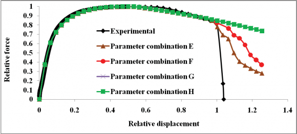
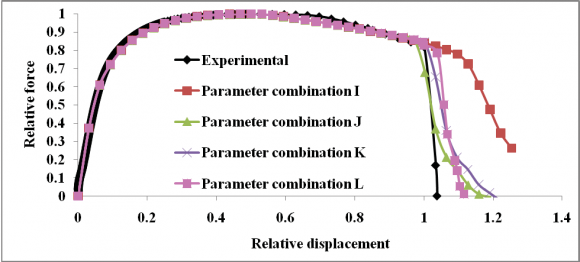
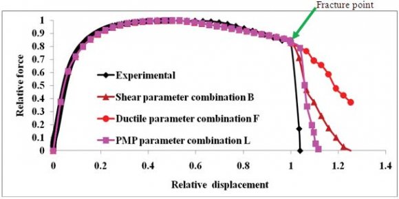
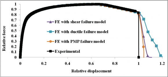
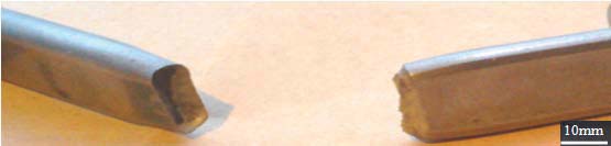
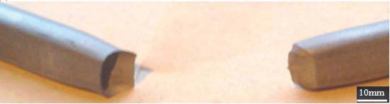
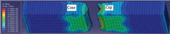
The normalized force-displacement curves (normalised with the experimental ultimate load and fracture point displacement values for confidentiality purposes) predicted by the simulations of the tensile testing of the 12mmx5mm wire specimens with varying shear, ductile and PMP model parameter combinations are shown in Figures 2,3 and 4 respectively. As shown in Figures 2-4 and as presented in Figure 5, the simulations with the shear parameters combination B, ductile parameters combination F and PMP parameters combination L predicted fracture points are the closest to the experimental fracture point. The phenomenological fitting to calibrate the damage parameters for the 12mmx7mm wire was conducted in a similar manner and the force-displacement curves obtained from the parameter combinations at which the FE simulations predicted force-displacement curves with approximately the same fracture point as the experimental curve are shown in Figure 6. The fractured laboratory specimens of the two wire sizes which exhibit a "cup and cone" fracture (flat fracture at the center and slant fracture at the outer regions of the specimen) are shown in Figure 7. The fracture shapes predicted by the simulations conducted with the varying shear, ductile and PMP model parameter combinations for the two wire sizes are the same. Consequently, only the fracture shapes predicted by the simulations conducted with the porous metal plasticity, ductile and shear failure models with modeling parameters that predicted force-displacement curves with approximately the same fracture point as the experimental curve for the 12mm x 5mm wire are shown in Figures 8a, b and c. The cup and cone fracture shape predicted by the simulation conducted with the shear failure models for the 12mm x 7mm wire are also presented in Figure 8d. and reliability) by their ability to predict forcedisplacement curves that agree with the experimental curve up to the fracture initiation point as published by Bernauer and Brocks, (2002); Dunand and Mohr, (2010); Li et al, (2011) and Rakin et al, (2004) among others, any of the shear, ductile and porous metal plasticity failure models considered in this work can be adjudged as an appropriate fracture model for the wire. However, as shown in Figures 8(c) and (d), for the two wire sizes considered, only the simulation conducted with the shear failure model predicted the "cup and cone" fracture exhibited by the fractured experimental wire specimens shown in Figures 2(a) and (b). The simulations conducted with the PMP and the ductile failure models predicted flat and slant fracture as shown in Figures 8(a) and (b) respectively. The ability of the shear fracture model alone to predict the "cup and cone" fracture exhibited by the fractured experimental specimen indicates that out of the three fracture models considered in this work, only the shear fracture model can be adjudged as the appropriate fracture model to predict the fracture performance of the typical wire for civil engineering application considered. The inability of the ductile and porous metal plasticity fracture models to predict the flat to slant fracture propagation, which represents the fracture path or sequence associated with the cup and cone fracture behaviour exhibited by the experimental fractured wire specimens does not makes the ductile and porous metal plasticity fracture models appropriate fracture models suitable for the prediction of the fracture performance of the wire.
9. Global Journal of Researches in Engineering
V.
10. Conclusion
This study has established that it is not sufficient to choose any of the shear, the ductile or the porous metal plasticity micromechanics-based fracture models as an appropriate fracture model to predict the fracture performance of carbon steel wires for civil engineering applications on the basis of a good agreement between the experimental and FE predicted force-displacement curve alone as is generally practiced. The need to consider the capability of the micromechanics based fracture model to predict the actual fracture shape exhibited by the experimental fractured wire specimens in choosing the appropriate fracture model has been demonstrated. Out of the shear, the ductile and the porous metal plasticity ductile failure models in-built in the Abaqus finite element code considered in this work, the shear failure model has been identified as the appropriate fracture model that is able to predict the "cup and cone" fracture shape or behaviour exhibited by the fractured experimental wire specimens. Thus, FE tensile testing simulation with the phenomenological shear fracture model can thus be used to predict the fracture performance of wires for civil/structural engineering applications. This study has thus identified an appropriate ductile fracture model that is capable of predicting the fracture performance of a typical carbon steel wire for civil engineering application in terms of the wires' force-displacement response and cup and cone fracture shape. It is hoped that, the use of FE tensile testing simulation with the phenomenological shear fracture model would be employed by engineers to predict the fracture performance of wires for civil engineering applications. This will allay the concerns on the fracture performance of the wires that are associated with the use of the traditional classical fracture mechanics approach for the prediction of the fracture performance of wires for civil engineering applications and serve as an alternative to using non-standardised traditional classical fracture mechanics specimens for the prediction of the fracture performance of wires for civil engineering reported in published literature.

| P Parameter combinations | Fracture strain | Shear stress ratio | Strain rate (s -1 ) | Parameter Ks |
| Parameters combination A | 0.2761 | 10 | 0.0001 | 0.3 |
| Parameters combination B | 0.345125 | 12.5 | 0.000125 | 0.3 |
| Parameters combination C | 0.41415 | 15 | 0.00015 | 0.3 |
| Parameters combination D | 0.5522 | 20 | 0.0002 | 0.3 |
| Fracture strain | Stress triaxaility | Strain rate (s -1 ) | |
| Parameters combination E | 33.238 | 3.3333 | 0.0001 |
| Parameters combination F | 36.5618 | 3.66663 | 0.00011 |
| Parameters combination G | 49.857 | 4.99995 | 0.00015 |
| Parameters combination H | 66.476 | 6.6666 | 0.0002 |
| Critical void volume | Total void volume fraction | ||
| Void volume fraction | fraction at failure | at failure | |
| Parameters combination I | 0.01 | 0.01 | 0.15 |
| Parameters combination J | 0.001 | 0.001 | 0.015 |
| Parameters combination K | 0.002 | 0.002 | 0.03 |
| Parameters combination L | 0.004 | 0.004 | 0.06 |
| III. |