1. Introduction
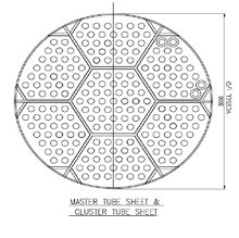
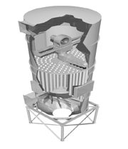
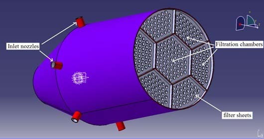
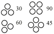
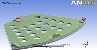
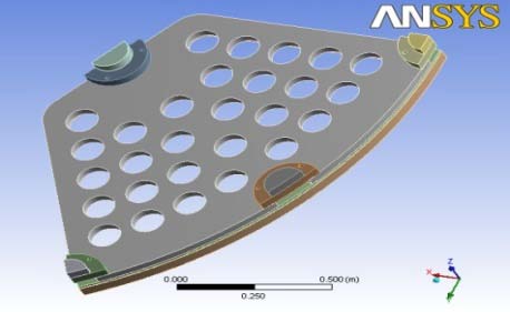
ilter Sheets are non standard components used in Oil & Natural gas Industry for filtration. The usual engineering practice is to extend the ever-current design is available with an increased factor of safety. Around the world, for environmental reasons, oil refineries equipped with a Filter Unit have to face the challenge of particulate emission reduction. The refinery would not be able to meet the tighter limits with its existing Filter Unit flue gas cleanup equipment. The 3 rd stage blowback filter option would enable industries to meet current particulate emission requirements and also get close to if not already meet particulate emission Author : M.E Design, D.Y.Patil college of engineering akurdi, pune . E-mail : [email protected] a number of years in advance of 2010 requirements. Existing tube sheet Filter assembly as shown in fig. 1 have less filtration capacity due to less number of filter tubes. Existing assembly model design is less advanced and flexible. We are going to increase the number of filter tube for increasing the filtration capacity.Fig. 2 shows proposed tube sheet assembly with increase number of tubes. The filtration capacity of proposed design can improve by using optimum pitch layout for filter candle. So to optimized the shape and weight of proposed filter sheet assembly considering various design constraints without affecting their functional characteristics. This entire unit is divided into seven different chambers. The central, hexagonal chamber has more filtration capacity than others. Each chamber is intented to filter a different gas allowing primary mixing of these gases. Inlet nozzles are provided to each chamber. Each inlet has flow control valve to control the flow of gas, thus enabling the control of percentile of each gas. Special filter candles, which remove flue gas particles as small as 2 micron, are proposed to be employed. The filter elements should be removed if the dirty filter P (differential pressure) is higher than the 0.7 bar as per operational guidelines. Fig- 4 shows the four pitch pattern. Among the four we select the 60 0 pitch pattern. The Design of proposed filter sheet are based on the following assumptions:
i) The plate is flat, of uniform thickness, and of homogeneous isotropic material. ii) The thickness is not more than about one-quarter of the least transverse dimension, and the maximum deflection is not more than about one-half the thickness.
Figure 4 : Pitch Pattern iii) All forces-loads and reactions are normal to the plane of the plate. iv) The plate is nowhere stressed beyond the elastic limit. For convenience in discussion, it will be assumed further that the plane of the plate is horizontal.
2. a) Manufacturing and Testing
Manufacturing of the filter sheet is done by Casting and machining .In machining the holes are Drilled and Reamed, then applying the Heat treating process. In Gulf countries they preferred Gas cutting or Rolled plates. For testing of Filter sheet, Non-Destructive Ultrasonic Testing machine is used. In other words, NDT allows parts and material to be inspected and measured without damaging them. Non-Linear Analysis of filter sheet is done by applying the following different seven conditions, for the same we consider 1/6 th portion of the filter sheet as shown in fig.
Figure 6 : Filter sheet assembly with different parts 1. To be analyzing given filter sheet for its self weight. 2. To be analyzing given filter sheet for differential pressure of 0.07MPa without self weight. 3. To be analyzing given filter sheet for differential pressure of 0.07MPa with self weight. 4. To be analyzing given filter sheet for hydro test with 2.5 times of given pressure of 0.07 MPa without self weight. 5. To be analyzing given filter sheet for hydro test with 2.5 times of given pressure of 0.07 MPa with self weight. 6. To be analyzing given filter sheet for back pressure of 0.07 MPa without self weight. 7. To be analyzing given filter sheet for back pressure of 0.07 MPa with self weight.
Top support and base support are welded to the shell. Therefore these are act as a fixed support. c) Non-Linearity Nonlinear structural behavior arises from a number of causes, which can be grouped into these principal categories: Geometric Non-linearity, Material Non-linearity, Contact Non-linearity.
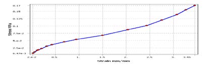
Contact forms a distinctive and important subset to the category of changing-status nonlinearities. When two bodies comes in contact but Homoginity is lost, Contact Non-linear Analysis is there and force is transmitted from one body to other body. In this project we have different materials Stainless Steel (SS), Structural steel (SA) & Neoprene rubber. Neoprene rubber has material nonlinearity as shown in following graphs.
There are five types of Contact Non-Linearity, these are-
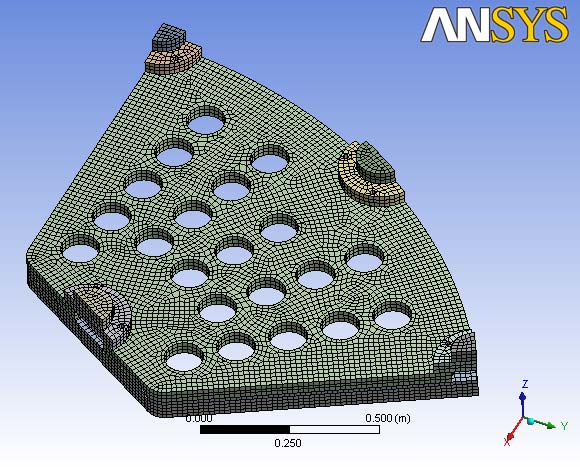
3. Meshing of Filter Sheet Assembly
4. Mass Modeling
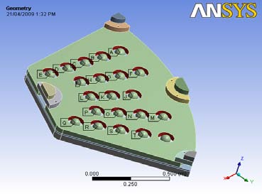
In filter sheet assembly, filters are to be hanged on filter sheet. These filters are shown as a mass model. IV.
5. The mass model is modeled by using RBE3 (Rigid Body Element).Figures 11 show the
6. Experimental Validation
For all new product lines, initial Design should follow SOC-306.
All new product equipments shall be tested at 2.5 times the operating pressure using Hydro test. The Hydro test shall have slow built up of pressure, from base pressure to test pressure over a period of 120 min. The equipment shall be maintained at test pressure for 30 min. The pressure shall be gradually reduced to base pressure within a period of 45 min. After test, all components shall be subjected to NDT (Non Destructive Test), the following NDT shall be done-Visual Inspection-No surface irregularities must be present and Pre Dyed components should have no loss of dye due to leakage.
Ultra Sonic Testing-Post Test, internal damage shall get amplified if any, and shall be recorded in an Ultra Sonic Test. The test performance of the assembly should be completely elastic, this shall be verified by checking the dimensions of product for any permanent yield. 2) The Mesh is satisfactorily fine enough to generate accurate results.
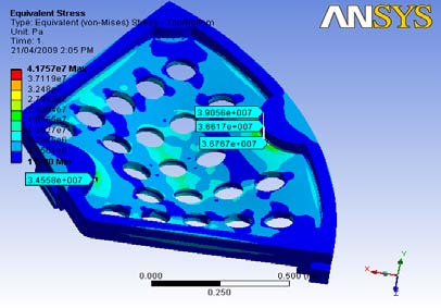
3) The boundary conditions were inspected. The maximum Stress in Filter sheet is 32 MPa, however nominal value if calculated is much lower, it satisfy FOS is 5.
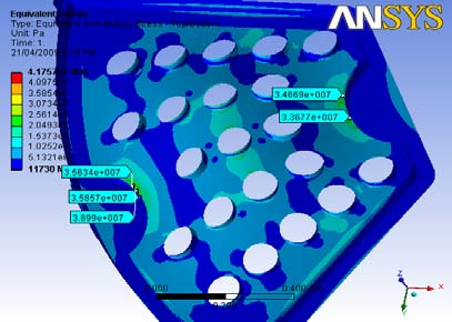
4) Gasket plate shows peak pressure of 34 MPa.however it is observed to significant stress raiser due to vicinity of contact and relatively less thickness of the plate compared to the other components. 5) Material Non Linearity may not be modeled in future analysis as it will have negligible effect on accuracy and unnecessary increases solution time.
V.
7. Design Optimization
As we see there is chance for design optimization, we checked for two different optimizations, Shape optimization and Thickness optimization a) Shape Optimization For shape optimization we tried with increasing filter mounting holes. While increasing filter mounting holes we didn't violate minimum centre distance between two holes. We could increase holes from 21 to 28. For 28 holes we analyze the filter sheet assembly as shown in fig 13 with keeping same boundary conditions as were for 21 holes. We directly analyzed for the worst case.
8. Mesh Sensitivity Analysis
Size of elements influences the convergence of the solution directly and hence it has to be chosen with care. If the size of elements is small, the final solution is expected to be more accurate. However, we have to remember that the use of elements of smaller size will also mean more computational time. As the number of elements increases, the size of each element must and consequently the accuracy of the model generally increases. Gasket plate having 12 mm thickness which is less as compared to others. The Gasket plate having contact on both sides Therefore there is not reliable stress concentration. Hence we should rely more on probe values as there is stress concentration. Currently inlet to central plate is not designed. If such a inlet is designed then its structural analysis is recommended in the future. In such analysis, we will have to reassess the performance of peripheral shell.

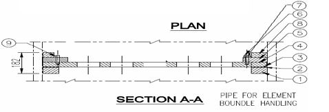
| 9 | LOCKING PIN | SS 304 | Dia16x 75 lg | 6 | REMOVABLE |
| 8 | TOP SUPPORT | SA 516 Gr.70 | 40 thk | 4 | WELDED TO SHELL |
| 7 | WASHER(M16) | SS 304 | M16 (spring) | 2 | STD |
| 6 | ALLEN BOLT | SS 304 | Dia16x 60lg | 2 | STD |
| 5 | PACKING PLATE | SS 304L | 40 thk | 4 | REMOVABLE |
| 4 | FILTER SHEET | SA 240 TYPE 304L | 40 thk | 1 | REMOVABLE |
| 3 | SQ.GASKET | RUBBER | Sq. 8X8 | 1 | GLUID TO TUBE SHEET |
| 2 | GASKET PLATE | SS 304L | 12 thk | 1 | REMOVABLE |
| 1 | BASE SUPPORT | SA 516 Gr.70 | 50 thk | 1 | WELDED TO SHELL |
| P.N. | DESCRIPTION | MATL | SIZE | QTY | REMARKS |
| Mesh size =15 mm = 0.015 m | |||||
| S.N | Conditions | Without Point Mass | With Point Mass | ||
| Von Mises Stress (Pa) Deformation (m) Von Mises Stress(Pa) Deformation (m) | |||||
| 1 | Self Weight | 7.2964 e5 | 2.2804 e-6 | 5.2877 e6 | 1.8405 e-5 |
| 2 | Differential | 1.6705 e7 | 5.1273 e-5 | 1.6705 e7 | 5.1273 e-5 |
| Pressure- | |||||
| Without wt | |||||
| 3 | Differential | 1.5976 e7 | 4.8994 e-5 | 1.1419 e7 | 3.2932 e-5 |
| Pressure-With wt | |||||
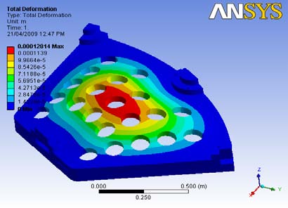
| 4 | Hydro test- | 4.1757 e7 | 0.00012814 | 4.1757 e7 | 0.00012814 |
| Without wt | |||||