1. Introduction
ow Power Factor in the power distribution system induces the energy crisis in the supply voltage. Most of industrial electric loads have a low power factor not transcending from 0.8 and thus imparts to the distribution losses [1][2][3][4].There are different methods of low power factor correction [1]. One of the impendent is to use a fixed capacitor as a source of reactive power for compensating local reactive power demand [5][6]. This approach is more reliable because it implies the count of lagging current in the power factor with very precise step setting in term of calculating the phase angle in power factor correction schemes [7].
Power factor correction is an old practice and different researchers are working hard to design and develop new system for the power factor correction. Fuld et al. developed a combine power factor control with buck and boost technique applied at three phase input supply, which present necessitate vantages at high AC voltage, desired output voltage, e.g. 400 V, wide input voltage varieties and no extra inrush clipper required [8].
Freitas et al. developed a dynamical study correspondence to the effects of AC generators (induction and synchronous machines) and distribution static synchronous compensator devices on the dynamic behavior of distribution networks [9].
Jones and Blackwell developed a technique for sustaining a synchronous motor at unity power factor (or minimum line current) from no-load to full-load conditions, insuring peak efficiency [10].
Kim et al. purposed a high-efficient line conditioner with excellent performance. The line conditioner comprises of a three-leg rectifier-inverter, which functioned as a boost converter and a buck converter [11].
Kiprakis and Wallace purposed the entailment of the enhanced capability of the synchronous generators at the distant ends of rural distribution networks where the line resistances were high and the (cos?) or the power factor ratios were small. Local voltage variation was specifically analyzed [12].
Above describe research work and much more has been presented in the area of power factor improvement of inductive load. However we have proposed a new algorithm for automatic detection and controlling of Power Factor for an inductive load comprising of both induction motors as well as resistive load. Proposed algorithm along with developed hardware setup works efficiently. Moreover detection and correction of power factor is very fast. Microcontroller manipulates the developed algorithm to measure the needed reactive power (VAR) that will be supplied through automatic switching of capacitor banks for the improvement of power factor of the load.
2. II.
3. Proposed System of Acpf
Microcontroller base automatic controlling of power factor with load monitoring is shown in Fig. 1. The principal element in the circuit is PIC Microcontroller (18F452) that manipulates with 11MHz crystal in this L
4. Global
5. Journal of Researches in Engineering
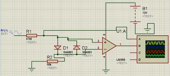
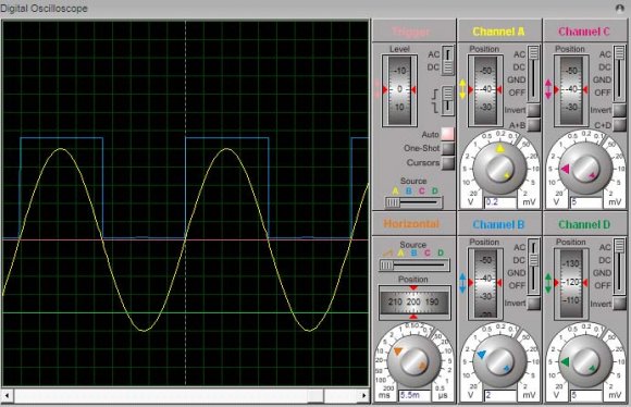
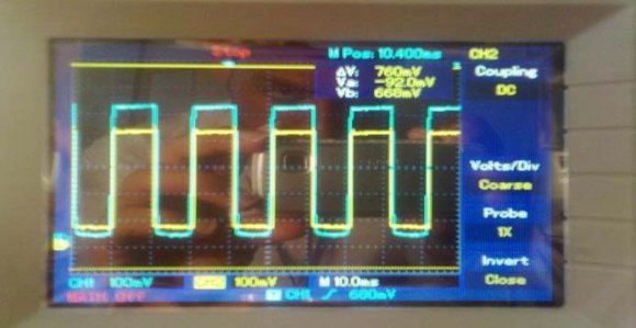
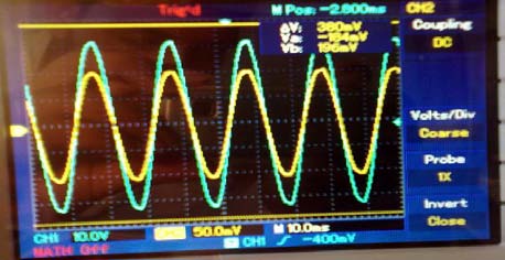
Volume XIII Issue II Version I 21 ( ) scheme. The current and voltage signal are acquired from the main AC line (L) by using Current Transformer and Potential Transformer. These acquired signals are then pass on to the zero crossing detector IC(ZCD I & ZCD V) individually that transposed both current and voltage waveforms to square-wave to make perceivable to the Microcontroller to observe the zero crossing of current and voltage at the same time instant. Bridge Rectifier for both current and voltage signals transposes the analog signal to the digital signal. Microcontroller read the RMS value for voltage and current used in its algorithm to select the value of in demand capacitor for the load to correct the power factor and monitors the behavior of the enduring load on the basis of current depleted by the load. Synchronizing circuit is developed to synchronize the zero cross detection circuit, Microcontroller and LCD with incoming supply voltage. In case of low power factor Microcontroller send out the signal to switching unit (relay) that will switch on the in demand value of capacitor. The tasks executed by the Microcontroller for correcting the low power factor by selecting the in demand value of capacitor and load monitoring are shown in Liquid Crystal Display (LCD). Set the Phi (?2) as a reference value equal to 0.9.and taking the cos inverse of 0.9 getting reference theta (??1).
? From the power angle diagram, the reactive power (VAR) utilized in circuit is given as:
tan 1 ? × =P VAR ? For reference VAR tan 1 2 ? × =P VAR? Required reactive power of the load is: ? Required value of impedance X c is:
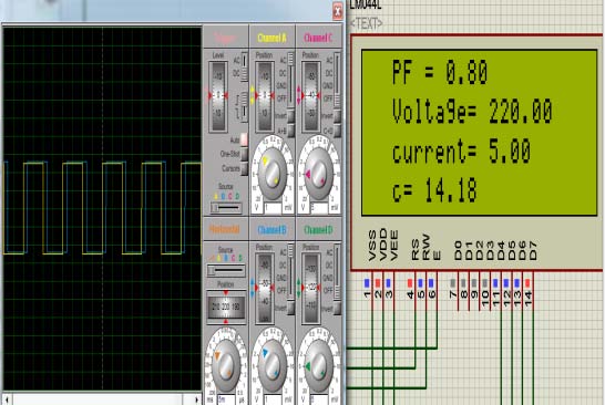
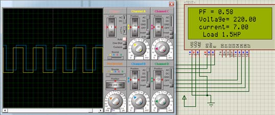
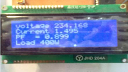
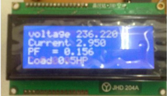
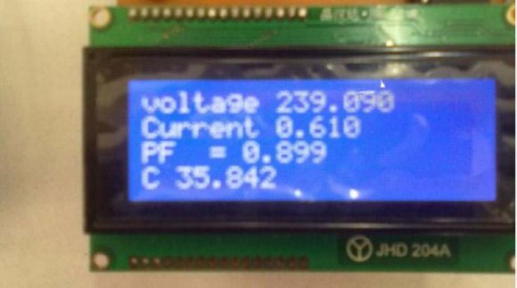
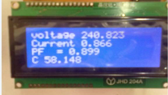
( )(3)(2) 5. In this case the power factor would be 0.9 as the set referenced value, so there is no insertion of capacitors. By the development of Microcontroller algorithm this 0.9 power factor shows unity power factor in actual.
(4)(5)6. Hardware Results and Discussion
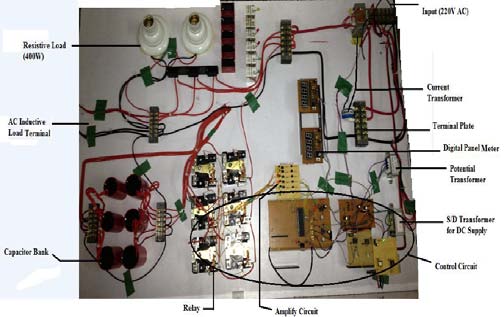
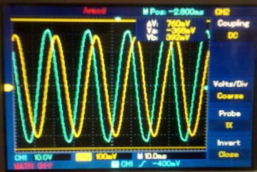
Main prototype model of the hardware is shown in Fig. 10. Second stage is concerned with zero crossing level detection by using an IC (LM358) for voltage and current, the incoming signals. Voltage signal can be acquired by using Opto-coupler (IC # 4N25) at the output of Potential Transformer for detection. Current signal can be acquired by using Current Transformer connected at main AC line.
In third stage block diagram represents the Automatic power factor control with continuously load monitoring of the system as shown in Fig. 10, the main part of the circuit is Microcontroller (18F452) with crystal of 11MHz.
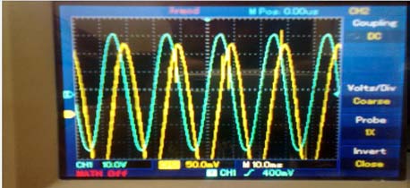
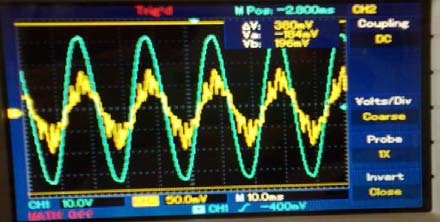
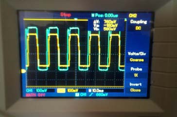
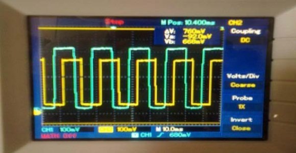
After acquiring voltage and current signals, they are then passed through the zero cross detector block (ZCD V and ZCD I), that converts both voltage and current waveforms in square-wave that are further provided to microcontroller to detect the delay between both the signals at the same time instant. Two bridge rectifier circuits are utilized to convert both AC voltage and current signal into pulsating DC signal that is further provided to ADC pin of Microcontroller for its conversion into digital signal, so that the microcontroller performs its further necessary task. After this the checking of RMS value for voltage and current is performed, these values are used in the algorithm of Microcontroller to select the capacitor of desired value to counteract the effect of low power factor of the load and monitor continuously which load is operated on the basis of current consumed by the load. Results of corrected power factor, needed capacitor value to correct the low power factor to desired value are shown on the LCD. factor would be 0.9 as referenced value, so there is no insertion of capacitors, as shown in Fig. 12 and 13.
7. Conclusions
This project work is carried out to design and implement the automatic power factor controlling system using PIC Microcontroller (18F452). PIC Microcontroller senses the power factor by continuously monitoring the load of the system, and then according to the lagging behavior of power factor due to load it performs the control action through a proper algorithm by switching capacitor bank through different relays and improves the power factor of the load. This project gives more reliable and user friendly power factor controlling system by continuously monitoring the load of the system. Measuring of power factor from load is achieved by using PIC Microcontroller developed algorithm to determine and trigger sufficient switching of capacitors in order to compensate demand of excessive reactive power locally, thus bringing power factor near to desired level.