1. Introduction
ow Power Factor in the power distribution system induces the energy crisis in the supply voltage. Most of industrial electric loads have a low power factor not transcending from 0.8 and thus impartsto the distribution losses [1][2][3][4]. There are different methods of power factor correction follow through with large lagging or non-liner loads [1]. One of the impendent is to use a variable fixed capacitor as reactive power compensating circuit also inductor brings reactive power to compensate the current for leading power factor [5][6]. This approach is more reliable because it implies the count of leading and lagging current in the power factor with very precise step setting in term of calculating the phase angle in power factor correction schemes [7].
Microcontroller manipulates its algorithm to measure the needed reactive power (VAR) that will necessitate to castigated the power factor of incoming load either the effect of the load on power factor is leading or lagging.
2. II. Block Diagram with Description
Microcontroller base automatic controlling of power factor with load monitoring is shown in Fig. 1, the principal element in the circuit is PIC Microcontroller (18F452)manipulate with 11MHz crystal in this scheme. The first step is about the initializing and ensuring the circuit, the microcontroller pins(AN0 and AN1) read the analog-to-digital converter (ADC) on real time basis. Microcontroller waits till the voltage and current signals yielded from the zero crossing detector circuit, provided to Microcontroller input pins (RC1 and RC2) which is fundamentally the capture module of the Microcontroller.
The following algorithm which is specially for automatically measuring the desired value of capacitor includes these steps.
? V rms and I rms is read by the Microcontroller using ADC ports. ? Power Factor is measured by the Microcontroller from manipulating of capture module for V and I signals.
? Real Power is measure by using formula P=I rms ×V rms ×cos? ? For angle detection by taking the Cos Inverse of phi (?) and getting the angle theta (??). ? Set the Phi2 as a Reference Value equal to 0.9.and taking the cos Inverse of 0.9 getting reference theta (??1).
3. Simulation Results
Automatic Controlling of power factor is completely tested on Software Proteus in which Simulation result are based on the leading or lagging power factor of the load. Simulations Results are based on include the purely resistive load and some case of inductive load.
4. Case 1
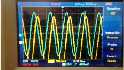
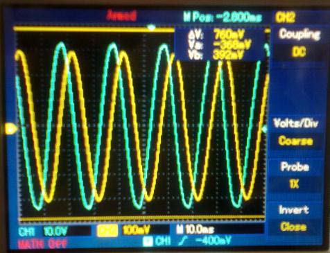
When resistive load is ON, there is no lagging in current and voltage signals and are in phase as shown in Fig. 5. In this case the power factor would be 0.9 as the referenced value, so there is no insertion of capacitors When Small Inductive Load is ON, there is phase delay in between current and voltage signals.
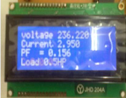
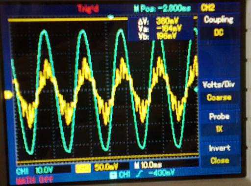
Microcontroller senses the delay produced by the load, and according to the delay, it inserts the desired value of capacitor to improve the power factor of the system. When an large inductive is ON, there is large phase delay in between current and voltage signals.
Microcontroller senses the delay produced by the load, and according to the delay, it inserts the desired value of capacitor to improve the power factor of the system.
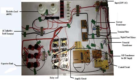
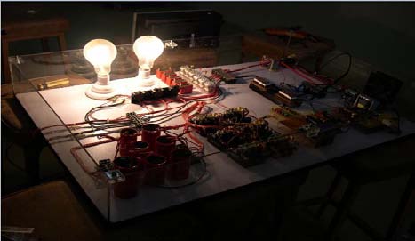
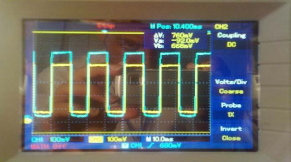
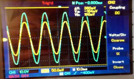
5. Hardware Results
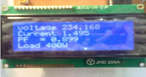
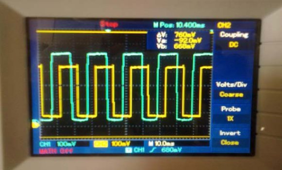
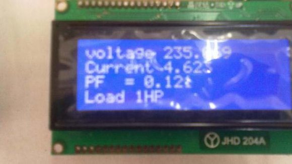
Main prototype model of the hardware is shown in Fig. 9. The current and voltage signals are taken from the main AC line by using Current and Potential Transformers. These signals are then pass form the zero cross detector IC (ZCD I and ZCD V) that converts both current and voltage waveform in square-wave that will further given to microcontroller to detect the zero crossing/delay between both the signals at the same time instant by using a bridge rectifier for both current and voltage square waves is then converted to a digital signal, so then the microcontroller performs its further necessary task i.e., checking of what RMS value for voltage and current that will use in the algorithm of microcontroller to select the capacitor for the desired value for the load and check/monitor continuously which load is operated on the basis of current consumed by the load. Results of leading or lagging power factor need Capacitor or inductor value to regain its original situation, and these results were shown on the LCD.
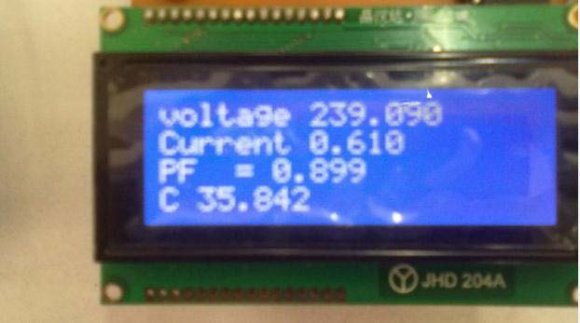
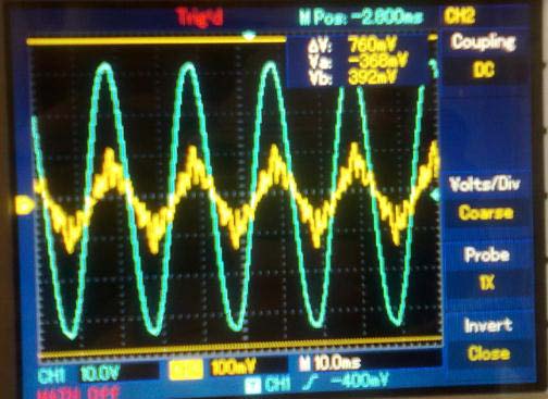
6. Case 1
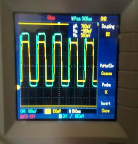
When resistive load is ON, as shown in Fig. 10: there is no phase delay between current and voltage signals and they are in phase. In this case the power factor would be 0.9 as referenced value, so there is no insertion of capacitors, as shown in Fig 10.
7. Conclusion
This project is an attempt to design and implement the automatic power factor controlling system using PIC Microcontroller (18F452). PIC Microcontroller senses the power factor by continuously monitoring the load of the system, and then according to the lagging behavior of power factor due to load it performs the control action through a proper algorithm by switching capacitor bank through different relays and improves the power factor of the load. This project gives more reliable and user friendly power factor controlling system by continuously monitoring the load of the system.