1. INTRODUCTION
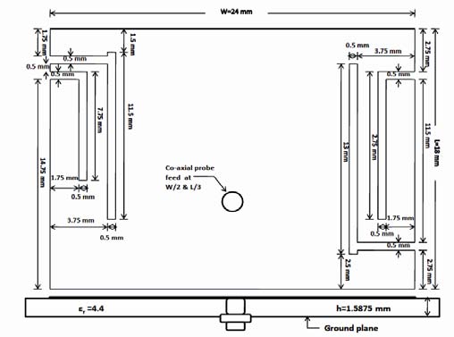
esign of compact microstrip antenna has become an interesting topic of research in recent years due to the demand for small antennas in wireless communication systems [1][2][3][4][5]. The development of antenna for wireless communication also requires an antenna with more than one operating frequency. Therefore one antena that has multiband characteristic is more desirable than having one antenna for each frequency band. Unlike normal antenna a defected structure introduces discontinuities on the signal plane and disturbs the shielded current distribution in signal plane [6].As a result apparent permittivity of the substrate varies as a function of frequency. The work to be presented in this paper is a compact microstrip antenna design obtained by the insertion of four L-shaped slot on the two sides of the patch.Two inverted slots are inserted on the left side and two slots are inserted on the right side (one inverted and one simple L slot) on the patch (Fig: 2).The work to be presented in this paper is directed towards the reduction of the size of the antenna as well as to operate the antenna in multi-frequencies. The proposed antenna (substrate with ?r=4.4) has four resonant frequencies and presents a size reduction of about 77.3% when compared to a conventional rectangular microstrip patch The simulation has been carried out by IE3D software which uses the MoM method [10]. Due to the Small size, low cost, low weight and multiband characteristics this antenna is a good candidate for application in Wireless communication system.
2. II.
3. ANTENNA STRUCTURE
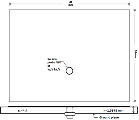
The configuration of the conventional antenna is shown in Figure 1. The antenna is a 24 mm x 18 mm rectangular patch. The substrate selected for this design is an FR4 epoxy with dielectric constant (?r) =4.4 and height of the substrate (h) =1.5875 mm. Co-axial probe feed of radius 0.5 mm with a simple ground plane arrangement is used at the point (0,-3) where the centre of the patch is considered at point (0, 0).Figure 2 shows the configuration of proposed antenna which is designed with the similar substrate. The antenna is also a 24 mm x 18 mm rectangular patch. Four L-shape slots which are created on the rectangular patch (as shown in the figure 2). The location of the coaxial probe-feed (radius =0.
4. SIMULATED RESULTS
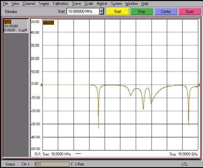
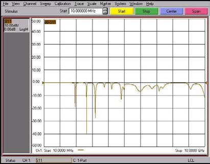
In this section, simulated return loss (of antenna 1 and 2) and normalized E-field and H-field radiation patterns (of antenna2) are shown. The simulated return loss of the conventional antenna (antenna 1) and the proposed antenna (antenna 2) are shown in fig. 3
5. and fig 4 respectively.
In conventional antenna only one resonant frequency is obtained below -10 dB which is 3.725 GHz and the return loss was found to be about -28. The simulated E plane and H plane radiation patterns for antenna 2 are shown in Figure 5-8.
Isolation between co-polarization and cross pola-rization is more than -15 dB for 1.845 GHz and it decreased with the increase of the frequency for 2.59 GHz and 3.29 GHz. 3 dB E-plane beamwidths are found to be reasonably good for all the cases.
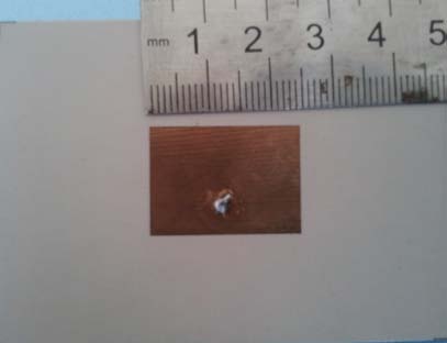
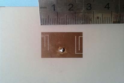
6. EXPERIMENTAL RESULTS
The prototype of the antenna 1 (conventional) and antenna 2 (proposed antenna) was fabricated and tested, which are shown in Fig. 9 Comparisons between the measured return loss with the simulated ones are shown in Fig. 13 and 14. The agreement between the simulated and measured data is reasonably good. The discrepancy between the measured and simulated results is due to the effect of improper soldering of SMA connector or fabrication tolerance.