1. I. INTRODUCTION
ur dependency on mechanical, aerospace, marine and civil engineering infrastructures is increasing day by day. These structures continue to be used, despite aging and the associated potential for damage accumulation. All these infrastructures are subjected to damage as a result of fatigue, overloading conditions, material degradation through environmental effects and unanticipated discrete events such as impacts or seismic events. Damage adversely affects the current or future performance of these infrastructures. Therefore, the interest in the ability to monitor the health of these infrastructures and damage identification at the earliest possible stage is very important to ensure performance standards, extend the operational lifespan, economical and maintain life-safety. Therefore the need for robust Author ? ? : Department of Mechanical Engineering, Andhra University, Visakhapatnam, Andhra Pradesh, India-530003. E-mail : [email protected] global damage identification methods that can be applied to complex structures has led to the development of methods that examine changes in the vibration parameter of the structure [1][2][3][4][5][6].
The actual implantation of vibration based damage identification using statistical process control for mechanical, aerospace, marine and civil engineering infrastructures starts with designing a proof of concept experiment. First, an excitation mechanism for vibration testing should be selected. The excitation methods fall into the two general categories of ambient and forced excitation methods. During ambient excitation, the input to a system is not generally measured. In contrast, excitation forces are usually applied in a controlled manner and measured when the forced excitation method is employed [7]. A resonance condition exists when the frequency of excitation due to any source coincides with a natural frequency of the structure. Therefore it is necessary to know the natural frequencies of the structure to be monitored prior to the experimentation. The modal analysis primarily concerns determination of natural frequencies and mode shapes of a dynamic structure. Once the modes are determined, they can be used in understanding the dynamic nature of the structure. Therefore Modal analysis is an important tool in vibration analysis, diagnosis, design, and control.
Vibration is a repetitive, periodic, or oscillatory response of an engineering structure. The rate of the vibration cycles is termed "frequency". Vibrations can naturally occur in an engineering structure and may be representative of its free and natural dynamic behavior. Vibrations may also be forced onto a structure through some form of excitation [8]. The excitation forces may be either generated internally within the dynamic system, or transmitted to the structure through an external source. When the frequency of the forcing excitation coincides with that of the natural motion, the structure will respond more vigorously with increased amplitude. This condition is known as resonance, and the associated frequency is called the resonant frequency. Natural, free vibration is a manifestation of the oscillatory behavior in engineering structures, as a result of repetitive interchange of kinetic and potential energies among components in the structure. O and energy dissipative characteristics. An engineering structure, when given an initial disturbance and allowed to execute free vibrations without a subsequent forcing excitation, will tend to do so at a particular "preferred" frequency and maintaining a particular "preferred" geometric shape. This frequency is termed a "natural frequency" of the structure, and the corresponding shape (or motion ratio) of the moving parts of the structure is termed a "mode shape." Any arbitrary motion of a vibrating structure can be represented in terms of its natural frequencies and mode shapes.
The limitations of the human mind are such that it cannot grasp the behavior of its complex structures in one operation. Thus the process of subdividing all complex structures into their individual components or "Finite elements" whose behavior is understood very easily, then rebuilding the original complex structures from the individual components or "Finite elements" to study its behavior. The term finite element was first used by Clough in 1960 [9] and gives the basic idea of Finite element method. The finite element method is a numerical method but is more general and powerful in its application to real world problems that involves complicated physics, geometry and/or boundary conditions. Engineering application of the Finite element method may be used in the three major categories of boundary value problems, namely 1) Equilibrium problems 2) Eigenvalue problems 3) Propagation or Transient problem
The generalized problem in free vibration is that of evaluating an Eigenvalue which is a measure of the frequency of vibration together with the corresponding eigenvector indicating the mode shapes. Actually the Eigenvalue problem may be considered as extension of the equilibrium problem in which critical values of certain parameters are determined in addition to the steady state configurations. The Eigenvalue-eigenvector calculation procedure falls into the three basic categories namely characteristic polynomial technique, vector iteration method and transformation method.
Aiming to investigate the vibration phenomena occurring in test structure first an experimental modal analysis (EMA) was conducted. The rapid development of finite-element techniques accompanied by tremendous technological progress in the field of personal computers allowed structural designers to use software packages like ANSYS for accurate simulation of structural behavior. In this work the experimental modal analysis (EMA) values are compared with the results obtained from ANSYS software version 11.0.
The main purpose of this paper is to present our perspective concerning the evolution of modal analysis of the test structure used for vibration based damage identification, experimentally and compared the results obtained from ANSYS software package version 11.0.
2. II.
3. SPECIFICATIONS OF THE TEST STRUCTURE
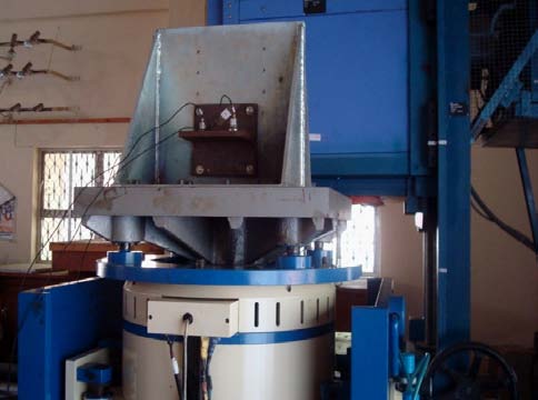
The applicability of the proposed vibration based damage identification technique to structural health monitoring problems is implemented using the cantilever plate like structure. The geometry considered for this purpose is shown in
4. III. EXPERIMENTAL MODAL ANALYSIS(EMA)
Modal analysis is vital to understand and optimize the inherent dynamic behavior of structures, leading to lighter, stronger, and safer structures with better performance. Experimental modal analysis is based on determining the modal parameters by testing, unlike analytical modal analysis, where the modal parameters are derived from finite element models (FEMs). There are two ways of doing experimental modal analysis [10][11][12][13][14][15]. They are 1) Classical modal analysis and 2) Operational modal analysis. In classical modal analysis frequency response functions (or impulse response functions) are calculated from measured input forces and output responses of a
The task of the analyzer is to convert analog time domain signal into digital frequency domain information compatible with digital computing and then to perform the required computations with these signals. Operational Modal Analysis is based on measuring only the output of a structure and using the ambient and operating forces as unmeasured input. It is used instead of classical mobility-based modal analysis for accurate modal identification under actual operating conditions, and in situations where it is difficult or impossible to control an artificial excitation of the structure. Classical modal analysis is a more mature technique in comparison to operational modal analysis, and is extremely useful in the design of engineering structures. Enhanced computing power and advances in finite element analysis (FEA) techniques have increased the fidelity of analytical model and in several cases have reduced the need for classical modal analysis, especially with legacy structures. However, classical testing will continue to be required to give engineers the confidence they need to continue to bring new product into development in today's competitive market. Classical modal analysis relies heavily on adhering to the four primary assumptions: 1) observability, 2) linearity. 3) time invariant and 4) reciprocity.
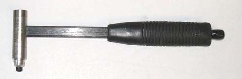
When a modal test is performed on a test structure the objective is to measure data from which the modal parameters -modal frequencies can be estimated. The most typical data used for parameter estimation are frequency response functions (FRFs), which use excitation input and the corresponding output of the test structure. Transient excitation is an input of short duration relative to the measured time record in contrast to random or sine inputs. The versatility of transient excitation techniques allows for several advantages over typical vibration shaker input. Quick diagnostics of structures with short setup times are possible. The most commonly used method of transient excitation for modal testing is the impact hammer. The impact hammer used to excite the test structure during experimental modal analysis is shown in Fig. 2.
5. Fig. 2 : Impact Hammer
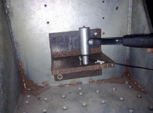
The idea of exciting a structure with an impact hammer actually involves striking the structure at a particular location and in particular direction with an impact hammer as shown in Fig. 3. Instrumented with a force transducer located behind the tip, the impact hammer measures the force used to excite the structure.
The force input and corresponding responses are then used to compute the FRFs. The FRFs obtained from the impact hammer test is shown in Fig. 4. Testing with impact hammer has some very distinct advantages. The input spectrum from the impact is flat out to the rolloff frequency with no holes in the spectrum. The technique can be very efficient and portable compared to the aligning and moving of shakers and their associated control systems.
6. Fig. 3 : Experimental setup for Impact Hammer test
The natural frequencies of the test structure which were identified with the peaks in FRFs plot and the values up to five kHz are tabulated in table 1.
7. MODAL ANALYSIS USING ANSYS
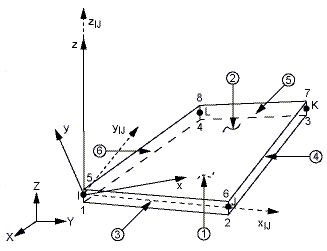
In this application the plate is subjected to transverse loads and in-plane loads and at any point inside the plate experiences both in-plane and lateral displacements. The natural frequencies for the test structure are calculated using SHELL63 element in ANSYS software version 11.0. SHELL63 has both bending and membrane capabilities. Both in-plane and normal loads are permitted for the SHELL63 element. The element has six degrees of freedom at each node i.e., translations in the nodal x, y, and z directions and rotations about the nodal x, y, and z-axes.
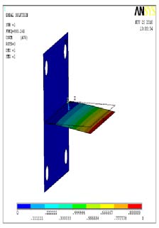
The geometry, node locations, and the coordinate system for SHELL63 element are shown in Fig. 5. The SHELL63 element is defined by four nodes, four thicknesses, elastic foundation stiffness, and the orthotropic material properties. Orthotropic material directions correspond to the element coordinate directions. In this application the thickness of the element is constant. The elastic foundation stiffness (EFS) is defined as the pressure required to produce a unit normal deflection of the foundation. The elastic foundation capability is bypassed if EFS is less than, or equal to, zero. The total number of nodes generated in the meshing of the test structure is 1289, and the total number of elements is found to be 1164. The first nine natural frequencies for the test structure are then calculated and the values are tabulated in table 2. The resultant deformation at each natural frequency and corresponding figures are given in Fig 6.
8. RESULTS AND DISCUSSIONS
The actual implantation of vibration based damage identification using statistical process control for mechanical, aerospace, marine and civil engineering infrastructures starts with designing a proof of concept experiment. First, an excitation mechanism for vibration testing should be selected. The excitation methods fall into the two general categories of ambient and forced excitation methods. A resonance condition exists when the frequency of excitation due to any source coincides with a natural frequency of the structure. Therefore it is necessary to know the natural frequencies of the structure to be monitored prior to the experimentation. Experimental and analytical modal analysis of a welded structure used for vibration based damage identification was conducted.
The natural frequencies obtained from the experimental modal analysis using impact hammer test and finite element modal analysis using ANSYS version 11.0 software package were compared. It has been observed that the natural frequencies obtained from the experiment are almost coinciding with the ANSYS results. The table 3 shows the comparison of natural frequencies obtained from the experiment and ANSYS; and it shows a quite satisfactory correlation.
9. CONCLUSIONS
This paper presents a systematic procedure and details of the use of experimental and analytical modal analysis of a welded structure used for vibration based damage identification. It has been concluded from the results that the natural frequencies obtained from the experimental modal analysis and ANSYS software version 11.0 shows a good consistency in comparison.

| Analysis (Impact Hammer Test) | |
| Mode Number | Natural Frequency in |
| Hz | |
| Package Version 11.0 | |
| Mode Number | Natural Frequency in Hz |
| 1 | 885.2 |
| 2 | 1731.0 |
| 3 | 2164.0 |
| 4 | 2626.0 |
| 5 | 4053.0 |
| 6 | 5454.0 |
| 7 | 6752.0 |
| 8 | 6859.0 |
| 9 | 6957.0 |
| Natural Frequencies of the test | ||
| Mode | structure in Hz | |
| Number | Experimentally | ANSYS |