1. Introduction
he wind power industry is becoming a focus of the national new energy industry. The blade as one of the core components of the wind turbine, its quality determines the healthy development of wind power industry. Due to the blade not only to withstand strong wind load, but also to bear the impact of sand and gravel, ultraviolet radiation and other external erosion in the process of work (Chen et al., 2014;Kong et al.,2005;Lee et al.,2015;Shi et al.,2011;Liu et al.,2013), coupled with wind power accidents occurred in recent years, so the wind vane full-size structure detection has become very important in the areas of research. The static test is the most important part of the blade certification in order to verify whether the blade is under ultimate load (such as 50 a worst hurricane). According to the third party authority Certification body Germany GL (Germanischer Lloyd) classification of the Guideline for the Certification of Wind Turbine (Germanischer Lloyd, 2003) and IEC61400-23 Full -scale Structural Testing of Wind Turbine Blades Testing standard, static load evaluation is the essential link of blade structure performance Testing. For the new development or process to make major changes in the leaves, is required to do a full-size static loading test, which the purpose is to verify the static strength of the blade. However, field tests show that the coupling force is stored between the loading force during the static test, loading force of any node changes, resulting in irregular fluctuations in the loading force of other nodes, resulting in the uncoordinated and uniform change between the loading forces. Resulting in serious distortion of the test data, so the coordinated control between the loading force becomes very important. Deflection measurement is a key parameter that must be collected during the static loading test. It is an important theoretical basis for checking whether the blade structure design is qualified. Most domestic and foreign scholars focus on testing control methods and equipment development, that is, how to improve the loading precision and made no mention of the blade deflection measurement. The adaptive sliding mode control algorithm is proposed in the literature (Benitro and Hedrick, 2009), which is applied to the three axis swing table control system, and a better control effect is obtained. The distributed control method is proposed in (Hua et al., 2010), and the feasibility of the method is proved by the theoretical analysis and experimental results. Currently in the process of static testing, only one rope sensor / laser rangefinder is usually used to realize single direction deflection measurement. For example, the full scale static test of large-scale wind turbine blade is only in a single direction of the deflection measurement in the literature (Wang et al.,2014; Li et al.,2013), which can't make accurate measurement of the three-dimensional space displacement of the wind turbine blade.
Aiming at the above problems, based on the analysis of the coupling law of load force and dynamic command method, this paper proposes a simple and accurate three -dimensional space displacement measurement model is constructed by using the geometric transformation method, and the corresponding data acquisition system is developed.
2. II. Wind Turbine Blade Full-Size Static Loading Scheme
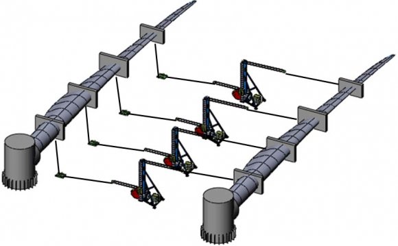
Wind turbine blade full-scale static loading scheme is shown in
Ithe blade is connected to the load node through the wire rope, and a tension sensor is connected in series between the wire rope to collect the current loading force. Each loading node is mainly composed of loading bracket, hydraulic winch, hydraulic drive system and electronic control system. Static loading test was usually divided into four stages, namely, according to the maximum load of 40%-60%-80%-100% for loading/ unloading, and the 100% stage requires a duration of not less than ten seconds. When the loading stage is completed, the load in reverse is order to unloading.
3. Fig. 1: Wind turbine blade full-scale static loading scheme
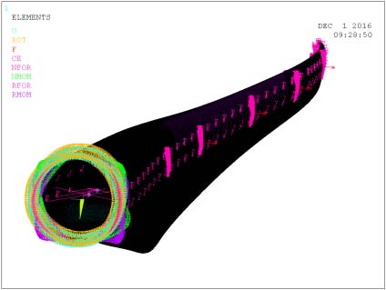
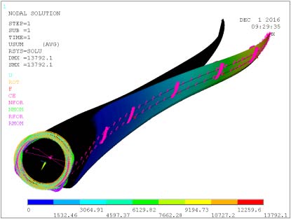
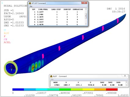
Taking the flapwise direction of aeroblade2.5-57wind turbine blades as the controlled object, the static loading test is carried out with four nodes. The four loading position are 14, 26, 32 and 40m, respectively along the spanwise direction of the blade. The loading force value of each node in the every stage is shown in Table 1. The finite element model of the blade under the above load is constructed in order to compare with the test results. The deformation of the blade under the above load is shown in Fig. 2. Take the 100% stage for example, the three-dimensional deflection simulation of the blade along the Span of 28m ? 42m ? 57 m are shown in Table 2. Three-dimensional deformation system is established. The four-node static loading test is carried out by using the horizontal loading method, which is shown in Fig. 3. PLC controller is applied to the static load scheme. In the measurement scheme, the blade tip is the measured point, under which three rope-type displacement sensors are fixed, and the sensor is fixed at the measured point, and finally the signal is transmitted to the monitoring system for data calculation and collection. Step 1: According to the Euler tetrahedron theory, the volume of tetrahedron oabc and o'abc (Respectively before and after deformation is recorded as V 1 and V 2 ) is expressed as:
2 2 2 2 2 2 2 2 2 2 2 2 1 2 2 2 2 2 2 2 2 2 2 2 2 2 2 2 1 / 2 1 (4 ( ) ( ) ( ) 12 ( ) ( )() )
4. V oa ob oc oa ob ab oa oc ac oc ob cb oc oa ob ab oa oc ob cb ob oa oc ac
Step 2: The circumference of ?abc is recorded as d1, according to Helen formula the area of ?abc is recorded as S1:
1 d ac bc ab = + +
(3)
1 1 1 1 1 ( -)( -)( -) 2 2 2 2 d d d d S ac ab bc = (4)Step 3: Find the height of ' oc and ' o d from the tetrahedral quadrature formula:
1 1 3 ' V oc S = (5) 2 1 3 ' V o d S = (6)Step 4: From the formula (8) to calculate the measured point o in the y direction of the precise change:
' ' y oc o d ? = ? (7)Step 5: Calculating the length of the c'b in the Rt?obc:
' 2 '2 c b ob oc = ?(8)Calculating the length of thedb in the Rt?o'db:
' 2 ' 2 db o b o d = ? (9)Calculating the length of the dc in the Rt?do'c:
2 2 ' ' dc o c o d = ? (10)Calculating the length of thead in the Rt?do' a: Step 8: According to the formula ( 17) and ( 18), the area S 4 of the ?adb is expressed as:
4 1 2 3 S S S S = ? ? (16) 4 1 2 S ab dn = × (17)Step 9: Common formula ( 17) and ( 18), find the value of dn, you can calculate the measured point o in the z direction of the precise deformation:
4 2S z dn ab ? = = (18)Step 10: Calculating the length of thenb in the Rt?dnb:
2 2 nb db nd = ? (19)Step 11: Common formula (21), find the value of nc, you can calculate the measured point o in the x direction of the precise deformation:
' ' x nc nb bc ? = = ?(20)IV.
5. Testverification a) Loading test
The LZ2.5-57-V4 blade is the main beam of glass fiber and the structure of double web. The main girder is 830mm wide and high modulus unidirectional cloth, and the shell skin is made of multi axial fiber cloth, sandwiched sandwich structure of Balsa and PVC, which can effectively provide the buckling resistance of the shell. The blade is a marine wind turbine, which is resistant to typhoon.
According to the above measurement scheme, this paper developed a space trajectory measurement system based on the mathematical model which is constructed above. The system consists of three pull rope type displacement sensors (Range: 0-30m, 4-20mA current output) and PLC analog acquisition module, the monitoring interface using software (MCGS) to configure. The pull rope type displacement sensor will transmit the analog signal to the PLC controller. The control system will get the precise deflection value after the mathematical operation, and will be transmitted to the man-machine interface through the RS485 Bus, which is shown in Fig. 5. Take the blade tip as an example, the test site is shown in Fig. 6. Three pull rope type displacement sensors were fixed on the ground, and the active ends of the three ropes were connected to the tip of blade. Test parameters were shown in Table In the process of static loading, the blade produces irregular space torsion, and all of them have deformation in three directions. Under the action of the above static load, the deflection measurement of the four stages in the static test of the blade is carried out respectively. The test results are shown in Fig. 7 From Fig. 7, it can be found that the blade has deflection in three directions. With the increase of loading load, the trend is increasing. By comparing the results of the finite element calculation with the test, the error of three directions is only 4.1%, 3.8% and 4.3%, which verifies the accuracy of the mathematical model.
6. V.
7. Conclusion
There are complex nonlinear and strong coupling characteristics under the wind turbine blade full-scale static test. The deflection is used as a key parameter to check whether the blade is qualified. At present, the measurement of its deflection is usually done with a rope sensor or laser range finder, this traditional method is not only poor precision, but also get the deflection change of a single direction. In this paper, a precise mathematical model of the threedimensional deflection of the blade is developed, and then the experimental verification is carried out, and the following conclusions are obtained.
1. Using three pull rope type displacement sensors and spatial geometric transformation method, a mathematical model of precision spatial deflection is deduced, which can calculate the accurate deflection change in three directions at the same time. 2. Based on the mathematical model, a set of spatial deflection measurement system was developed. The blade tip change which in a certain type of wind turbine blade static test as a testing object, and the tip system was measured by the measuring system. The results show that the system can track the spatial trajectory of the blade tip, and the data acquisition result is stable and accurate. In addition, since the rope sensor has been stretched during the test, it does not produce severe jitter and improves the stability of the test results. 3. The mathematical model and system can not only measure the irregular torsion caused by the static test of wind power blade, but also apply to the space deformation measurement of irregular parts such as cantilever beam, which has extremely wide application prospect of engineering application.
It was successfully applied to the full-scale static test of four nodes wind turbine blade. The above research results can provide a solid theoretical basis and detailed experimental data for the next step of blade re-design, which has great engineering application value.


| Load Step | 13.0m | 24.0m | 33.0m | 46.0m |
| 40% up/KN | 37.85 | 39.07 | 27.34 | 53.09 |
| 60% up/KN | 56.78 | 58.24 | 40.42 | 79.98 |
| 80% up/KN | 75.71 | 78.13 | 52.78 | 106.87 |
| 100%/KN | 94.63 | 97.60 | 67.76 | 134.47 |
| Location | 28m | 42m | 57m |
| x direction/m | 0.258 | 1.015 | 5.045 |
| y direction/m | 0.143 | 0.305 | 1.256 |
| z direction/m | 2.431 | 6.045 | 17.032 |
| III. Three-Dimensional Measurement | |||
| Mathematical Model | |||
| Parameter | Value |
| Blade rated power /MW | 2.5 |
| Blade length/m | 57 |
| Number of loading nodes/ea | 4 |
| Tension sensor model | DBSL-25T |
| Maximum capacity of loading nodes/KN | 250 |
| Room temperature/? | 29 |
| Humidity/RH | 56 |
| b) Result analysis |