1.
Introduction measurement or control system is made up of the acquisition of information gathered by a sensor or transducer, the processing of the said information and presentation of results, so that they can be perceived and interpreted by the human observer [1]. There are generally six types of signals in the field of engineering namely mechanical, thermal, magnetic, electrical, optical and molecular (chemical). In this paper, signal measurements are made using a MEMS (Microelectromechanical Systems) based magnetic field sensor. Magnetic field sensors are used in areas of medicine, telephony mobile, steel industry, automotive industry, GPS navigation, among other areas. A Microelectromechanical System (MEMS) is a device with dimensions of small microns that incorporate electrical and mechanical components. Hence, MEMS are used to reduce size, save energy consumption and decrease the cost of magnetic field sensors [2].
In this paper we analyze and test a magnetic field sensor based on MEMS technology with an Arduino board which will be used to power and acquire the signal generated by the sensor along with an electronic system designed to condition the acquired Author ? ? ?: Tamale Technical University. e-mails: [email protected], [email protected], [email protected] signal so that it can be measured linearly. The Transmission of the conditioned signal will be carried out wirelessly.
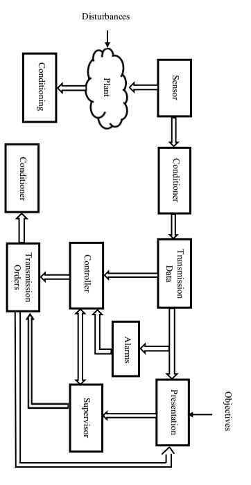
Fig. 1: General structure of a measurement and control system [1] Magnetic field sensors are devices in which a physical quantity can produce an alteration of a magnetic field or an electric field, without a change in inductance or capacitance. These sensors detect magnetic fields caused by magnets or electrical currents.
The strength of a magnetic field can be measured using different types of techniques with each technique having unique properties that make it more suitable for specific applications. These applications can range from sensing the presence of any change in the magnetic field, to accurately measure the scalar and vector properties of a magnetic field. Magnetic field sensors can be divided into two types:
? Vector component. ? Scalar Magnitude.2. A
3. Global Journal of Researches in Engineering ( ) Volume XX Issue IV Version I
Vector type sensors can be divided into sensors that are used to measure Low Field (< 1mT) and High Field (> 1mT). The instruments that measure low fields are commonly known as magnetometers, and Instruments that measure high fields are usually referred to as Gaussimeters.
4. a) MEMS Technology Based Sensor
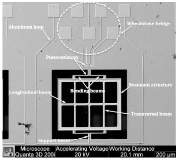
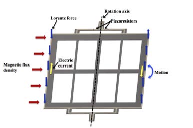
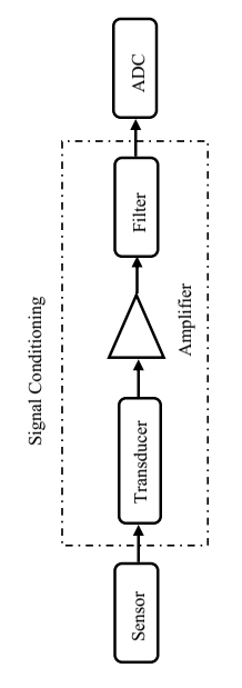
The MEMS sensor detects the flux density of a magnetic field using the Lorentz force as shown in Figure 2. It has a resonant structure of 700 x 600 x 5 µm, with a rectangular circuit, four flexible silicon beams and an arrangement of longitudinal and transverse silicon beams. The resonant structure is attached to a silicon substrate through two beams of torsion (60 x 40 x 5 µm). The MEMS sensor also contains a jumper Wheatstone bridge with four p-type piezoresistors, two of them are positioned on flexible beams and the other two on the surface of the silicon substrate [3]. The MEMS sensor operates with the Lorentz force, which is generated by the interaction between a magnetic flux density and an excitation current sinusoidal through an aluminum circuit, as shown in Figure 3. The magnetic flux density is applied in the longitudinal direction of the resonant structure [3]. The Lorentz force is amplified when the resonant structure operates at its first resonant frequency. This causes a longitudinal deformation in the two piezoresistors located on the flexible beams, causing the initial resistances to change. This generates a variation in the voltage output of the Wheatstone bridge. Consequently, the electrical voltage signal from the bridge becomes proportional to the magnetic flux density applied to the MEMS sensor [4]. Signal conditioners are measuring elements that offer from an output signal of an electrical sensor, a signal suitable for displayed or used in a later process.
The functions of signal conditioners are: filtering, amplification, modulation and demodulation, and impedance matching.
5. Fig. 4: Signal conditioning
A filter is a device that separates the signals according to their frequency or other criteria. The filter can be located at the input or intermediate stage. When the filter is located in the input stage, it can be of electrical, mechanical, pneumatic, thermal, or electromagnetic type. When the filter is located in an intermediate stage, it is normally of the electrical type.
An amplifier is a device that, by using energy, magnifies the amplitude of a phenomenon. For this purpose, amplifiers used are mainly operational amplifiers with some key characteristics such as:
? High input resistance (hundreds of M?).
6. ? Low output resistance (below 1?).
? Large open loop gain (104 to 106).
? Large CMRR (common mode rejection ratio) (Gd / Gc). ? Good range of operating frequencies.
? Low sensitivity to variations in the power supply.
? Great stability at ambient temperature change.
Modulation is a set of techniques for transporting information over a carrier wave, normally sine. This allows for a better use of the communication channel transmitting more information simultaneously and protecting it from noise and interference.
Demodulation as its name indicates, is the reverse of modulation. It is the set of techniques to recover the information carried on a carrier wave. So in any telecommunication there will always be at least one modulator-demodulator pair.
The objective of impedance matching is for maximum transfer of power to exist so that all the energy sent by the source are received by powered devices. If the source has an impedance less than connected device, it is required to place resistance equal to the impedance of the source in parallel with the high impedance device.
7. III.
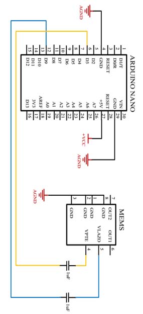
8. System Design a) Sensor Feed
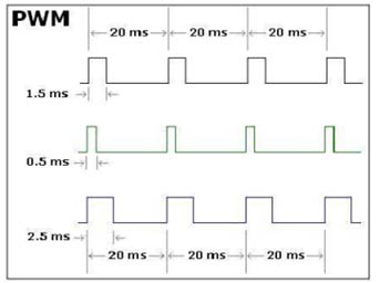
The sensor is powered by two signals, one with a frequency of 1 KHz and the other with a frequency of 14.376 KHz. At these frequencies, the sensor has a response with a linear behavior within a range of 40 µT to 2000 µT. To generate these signals, the Arduino Nano The Arduino Nano board has 6 pins that provide PWM (Pulse-width modulation) output. PWM or pulse width modulation is a technique that is used to simulate a variable analog output to obtain a digital output. The resulting signal is a square wave, and its great feature is that the duration can be varied with a pulse when it is positive or 5 volts. However, this variation does not affect the duration between each pulse and cycle, which means that the signal frequency remains the same.
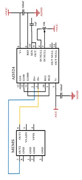
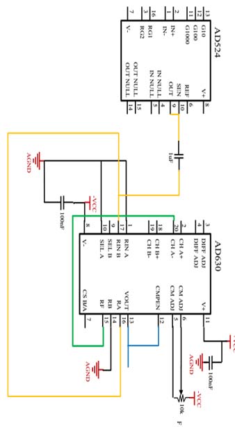
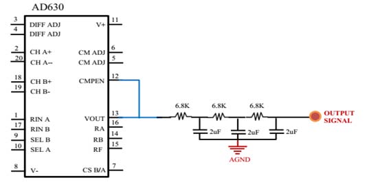
Figure 5 shows the general PWM representation scheme. The importance of PWM in this work is fundamental, since using this technique seeks to generate the square and sinusoidal signals required by the MEMS sensor. The Arduino Nano is initially programmed to generate the PWM signal at a frequency of 490Hz. It is generated at this frequency because it is the default frequency for PWM on pin D9 of the Arduino. The signal generation is done using software through the programming of the ATMega328 chip incorporated in the Arduino Nano board. For the amplification stage of the output signal of the MEMS sensor, the AD524 integrated circuit, which is an instrumentation amplifier designed for high precision data acquisition applications is used. This amplifier has three programmable gain pins of 10, 100, and 1000. It operates with a supply voltage range of ± 6V to ± 18V. The frequency of operation is 25MHz so the output signal is not distorted with respect to the input signal. The programmable pins of the amplifier are 13, 12 and 11 for gains of 10, 100 and 1000 respectively. For the amplification of the MEMS sensor signal a gain of 1000 is needed per what pin 11 of the amplifier is used. The circuit connection of the amplification of the MEMS sensor signal is shown in Figure 7. To demodulate the signal generated by the instrumentation amplifier, the AD630 integrated circuit is used. This integrated circuit allows demodulation of a signal at a high speed and precision. The AD630 operates with a supply voltage range of ± 5V to ± 18V. The frequency of operation is approximately 350 KHz, hence the signal output is not distorted with respect to the input signal. The connection scheme for the demodulation of the amplified sensor signal MEMS is shown in Figure 8. The AD630's output signal connects to a thirdorder low-pass filter to eliminate noise in the signal, leaving the connection diagram as shown in Figure 9. The output from the third order low pass filter is the ultimate signal of the system and the desired signal to be visualized and analyzed with a computer.
9. Results
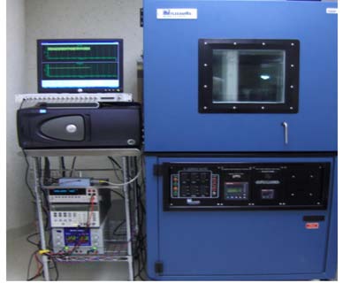
Figure 10 shows the experimental setup used for the characterization of the signal conditioning system inside an environmental chamber along with the virtual instrument, which can be run on a computer connected to the PCI-DAS6031 data acquisition card. The electrical response of the sensor to atmospheric pressure is obtained experimentally using a Helmholtz coil to apply magnetic densities of -150 µT to +150 µT. For this test the signal conditioning system of the magnetic field sensor is inserted into an environmental chamber in order to maintain a controlled temperature of 26 °C. The sensor is placed in the center of the Helmholtz coil, where the magnetic field density is homogeneous. The bridge Wheat stone's sensor is powered with 1 kHz signal and aluminum loop with 14.376 signal is fed at a current of 20mA. From the virtual instrument the output voltage of the system could be measured electronically using the data acquisition card.
10. Conclusion
Because the MEMS sensor generates a very small output signal, in the microvolt scale, it is necessary to amplify this signal to obtain one that is on the millivolt scale. For this stage of amplification, we search an amplifier that works with a supply voltage of 9volts to use a single power supply for the entire electronic system. The signal amplified by the AD524 is a modulated signal, so it is necessary to undertake a signal demodulation step to recover the source signal from the amplified signal. For this, a demodulator is sought, like the other devices which operates on a 9volt supply voltage. When testing the demodulator, it is observed that there was curl in the demodulated signal. Due to this, a further stage of filtering the signal to eliminate noise in it becomes necessary. For the filtering stage, a third order low pass filter was designed. When passing the signal demodulated by this filter the unwanted ripple in the signal is removed, obtaining an expected analog signal.
As can be seen in the previous points, an improvement in the design of the signal acquisition system of a magnetic field sensor based on MEMS technology has been successful by a decrease in electronic components on the motherboard, as well as lower consumption of energy, changing the 15volts power supply for a 9volts is enough to power the Arduino board and other components.