1. Introduction
he solutions envisaged to keep the moving plate (rotor) in translation at very high speed can be hydrodynamic or magnetic.
Hydrodynamic solutions can be implemented within the linear electric machine requiring high translation speeds. The principle is based on the use of on which the part in translation will be supported during its movement. The fluid in question can be a liquid lubricant such as oil or a gaseous carrier such as air under pressure. In both cases the film thus formed between the two fixed stators and the moving plate of the machine is very thin in relation to the total system. The capacities of this solution are very high. For example, the large alternators of the turbines of the Grand Maison dam, located in the French Alpes, have a vertical axis of rotation and are equipped with axial oil stops for rotational guidance.
Magnetic fields are used to generate forces in many actuators. These actuators only operate with one degree of freedom. In the case of a linear machine in translation, for example, only magnetic forces that allow the moving plate (rotor) to move are used. When all the degrees of freedom of a moving plate in magnetic solution are controlled by electromagnets, the magnetic solution is said to be active as in figure 1 (the current is servo-controlled to keep the moving plate in a fixed position. The magnetic solution needs a power supply to operate, a power supply, a control and position sensors are required). In order to simplify some solutions, magnetic solutions based on magnets can be used. Stability will be ensured by one or more active bearings. These solutions are called passive solutions (passive solutions are autonomous and very simple to realize. They are with permanent magnets or variable reluctance).
2. Fig. 1: Active principle
Magnetic solutions are used in areas where mechanical systems reach their limits: high speed range (the absence of contact in a magnetic solution makes it possible to reach very high speeds); a range in which friction and wear must be minimized (friction is almost non-existent in a fully magnetic solution because there is no contact between moving and stationary parts and the bearing life is unlimited) ; a range in which high precision is required (an active magnetic solution, controlled by a servo drive, allows the moving plate to be positioned with great precision) and, a range in which temperature variation is significant (a magnetic solution, made of suitable materials, is capable of operating at extreme temperatures) [1] [2].
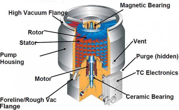
Magnetic solutions are used in very different fields. They can support parts weighing a few grams such as electric meter disks up to machines weighing several tons such as linear electric machines. The main applications are: the application of magnetic solutions in space is the use of flywheels to stabilize a satellite or to store energy. Magnetic solutions can be used to equip machining spindles (Figure 2) and turbo molecular pumps can be used to obtain a very high vacuum thanks to a turbine rotating at high speed, (Figure 3). Industrial solutions are more focused on the hydrodynamic regime. There are self-lubricating plates or plates on the market, impregnated with specific oils and coated with a solid lubricating film: molybdenum disulfide (MoS2). The self-lubricating plates allow a continuous operation. The performance and safety of the self-lubricating plates depend on the grade of metal alloy and the nature of the lubricant. The performance is related to operating and environmental conditions: dynamic load; speed; temperature; atmosphere and corrosive or non-oil compatible liquids. Maintenance is almost non-existent; the operation of the plates requires no maintenance. The presence of the lubricant film is permanent, resulting in a good coefficient of friction, silent operation and good corrosion resistance.
3. Linear Electric Machine Description
The stators of the linear electric machine are made of a magnetic circuit in M300-35A rectangular form, in laminated sheets equipped with the slots intended for three-phase winding aluminum bars. The magnetic circuit is laminated in stacked plates cut to their thickness. The number of stacked plates is proportional to the width of the magnetic circuit. The plate is punch-cut in a single operation from a strip of sheet metal, first insulated on both sides by a phenolic class H varnish. The plate hole profile has a circle shaped that will help stack plates for the appropriate height of the magnetic circuit to be dipped in the oven.
The side of the plate bore has 36 slots intended to receive the winding bars after stacking [5].
The winding is three-phase-series bar star. Each bar is a rectangular aluminum section to ensure transverse field compensation of Roëbel slot process. Bar winding has several advantages over traditional winding: good slot filling factor (greater than 95%); minimization of solid insulation and the potential difference between bars; better performance; and good thermal behavior in the slot.
Linear electric machine is protected by an aluminum cover called enclosure against ingress of moisture, dust, atmospheric impurities and any foreign materials.
The moving plate consists of a permanent magnets made of NdFeB (alternating North-South), which are magnetized in the transversal direction. The magnets are glued to a brass frame. The friction sheet is made of bronze 0.1 mm thick to ensure strength and mechanical rigidity. Anaerobic glue (polymerized in the absence of air) of acrylic type is used. The linear electric motor is a parallelepipedic structure with two air gaps (Fig. 4).
4. Centering and Plating Forces
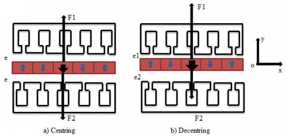
The main problem encountered in the design of air gap structure is in the control of the mechanical clearances necessary to allow the permanent movement of the moving plate [6], [7], [8]. This problem is very difficult to control due to the magnetic gap which must be as small as possible to avoid penalizing the tangential magnetic pressure. The moving plate is thin in the multi-air gap structure and therefore not very rigid. Moving plates made of magnets, therefore, tend to rub against the fixed stators. It is necessary to control the forces that are perpendicular to the active surfaces. In Linear machines have been and continue to be designed considering a large variety of topologies. Linear machines are flat or tubular. They have a long stator: the mover is shorter than the stator or a short stator: the mover is longer than the stator. The stator slots are of single layer type or double layer one.Beyond energy efficiency, linear machine concepts exhibit: high velocity, high acceleration, high accuracy of the position sensing and high lifetime with less maintenance [3] [4]. linear electrical machines with a parallelepipedic multi-each position, figure 5, we have: e + e = e 1 + e 2 = 2e; e 1 = e -e y ; e 2 = e + e y ; e theoretical mechanical air gap; e 1 upper air gap; e 2 lower air gap and e y offset; F 1 attraction force created by stator 1; F 2 attraction force created by stator 2; F the sum of the forces applied to the moving plate. Each of the two stators exerts an attractive force on the moving plate (rotor). These two oppositely directed forces have a modulus which is related to the size of the air gap facing each other, as well as to the current flowing through the coils necessary for position control. Let us consider the equilibrium of the moving plate, i.e. the sum of the forces along the yaxis.
Under ideal conditions, normal forces are the same and counteract from side to side (the weight of the moving plate is neglected) (Figure 5a). Force F 1 should be of the same modulus as force F 2 , the equilibrium position of the moving plate being centered in the middle of the two stationary stators.
5. Fig. 5: Centring and decentring force
There is no perfect centering in practice. The air gap exists and a driving force is created giving rise to a normal force which will influence the performance of the linear electric machine. This asymmetrical position generates a force difference, applied perpendicularly to the movement, which tends to create friction between fixed and moving plate (figure 5b). The balance must be restored ? F ?? = 0 ( F 1 ????? + F 2 ????? + F ?? = 0). The moving plate must move towards the stator opposite the direction of application of force F in order to restore the balance. This is because the smaller the air gap, the higher the attractive force. By decreasing the air gap on one side and thus increasing it on the other, the equilibrium of forces is achieved within a certain limit. This limit is conditioned by the size of the air gap as well as the normal stiffness constant. The magnetic balance of the moving plate is very unstable. The phenomenon described above has caused many failures in the design of linear electrical machines with a multi-air gap structure with guided or friction plates. Operation is affected by high wear of the friction interfaces (friction).
In order to fully understand how magnetic solutions work; they must be compared to a mechanical system. When the stiffness constant is positive, it is assimilated to a spring which will oppose the displacement. Conversely, when the stiffness constant is negative, the solution favors deviation from the original position.
IV.
6. Calculation of Normal Force
The air gap is very important in the electromagnetic parameterization of a linear electric machine with a multi-air gap structure with guided or friction plates. This normal force which depends on the air gap is strictly related to the mutual position of all permanent magnets and stators [9], [10].
7. a) Analytical calculation of force
As the magnetic circuit changes its shape during operation (displacement of the moving plate), the force is calculated analytically using the virtual working principle and Maxwell's torsor methods. Here we use the principle of virtual work.
Faraday's Law of Induction presents the voltage induced in the winding, which creates a current that tends to resist flux changes. The voltage equation for the winding is written as follows: The transformed energy is given by the equation:
??W = uidt = Ri 2 dt + Nid?(3)(Ri 2 dt) is energy transformed into heat and Nid? is reversible energy. The virtual displacement principle allows the driving force to be calculated analytically. The calculation is carried out at maximum displacement.
F = ?w (x) ?x = ? ?x ?? (? HdB)dV v ?(4)x is the displacement of the mobile (m); W: the magnetic energy (J); B: magnetic induction (T); H: magnetic field (A/m) and V: volume (m 3 ).
8. b) Calculation by the finite element method
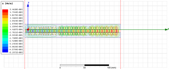
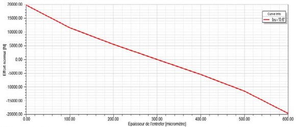
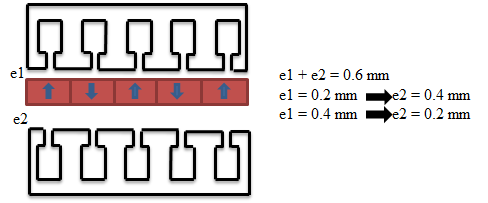
The finite element method uses the same principle; it is applied over the pattern of the linear electric machine. The table below gives all the dimensions of the prototype. The suspension consists of NdFeB (neodymium-iron-boron) permanent magnets and the two stationary stators are made of metal sheet grade M300-35A, where on the side of stator 1 there is an air gap of 0.2 mm, on the side of stator 2 there is an air gap of 0.4 mm (figure 8).
Fig. 8: Cross-section of the linear machine From Figure 7, we can estimate that linearity is important enough to consider normal stiffness to be constant. We can deduce the following characteristics:
The normal stiffness (N/m) is equal to the variation of the normal stress on the variation of the air gap.
The current stiffness (N/A/mm²) is equal to the variation of the total force on the variation of the current density.
These calculated parameters are used to dimension the analytical model.
The simple model established around an operating point makes it possible to control the suspension, in Laplace's formalism, by placing oneself around any point to be enslaved.
The mechanics allows us to link the normal force F N (p) with the acceleration ? N (p) and the mass of the moving plate (M).
? N (p) = 1 M F N (p)(5)By integrating the acceleration, we obtain the velocity V N (p), and by integrating again, the position y(p).
The normal force is proportional to the square of the induction (B 2 ), thus the square of the flux (? 2 ).
F N = B 2 2? 0 S = ? 2 2? 0 S(7)V.
9. Control/Command Mode a) Spring compensation
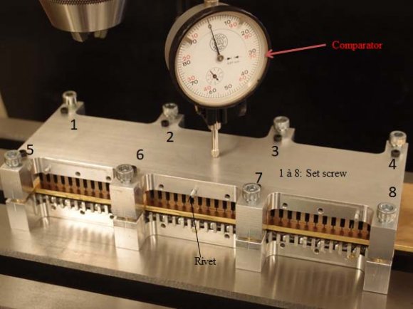
The principle is to take up exactly the force of attraction between the moving plate and the two stationary stators by means of an adjustable spreading force between the two stationary stators, see figure 4.Adjusting the gap between the two stators to cancel friction. Flatness is obtained from the dial gauge by manipulating the eight screws of the guide device.
10. b) Compensation by coupling tangential and normal forces
The coupling of forces to compensate for frictional forces is a path to be explored. The variation in spring stiffness creates a damping effect to compensate for friction forces. The principle consists in modifying the spring stiffness during the operation of the linear parallelepipedic electric machine (displacement of the moving plate) in order to compensate the friction forces.
? In the centered position (moving plate), the sound pressure at the output of the sound line delivers a sound power to the moving plate. It moves with a speed V.
? 0<t<td, the compensating force created by the springs provides a reaction force to keep the moving plate centred during operation of the linear parallelepipedic electric machine, where td is the time taken to cover the half stroke.
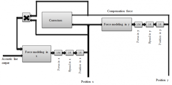
The coupling between two forces to transfer energy to a servo force, allows the recovery of vibration energy from the moving plate, as shown in figure 9.
11. Fig. 9: Coupling of tangential and normal forces
At the level of the correctors, the normal force (in y) can be controlled by a conventional corrector. The addition of another proportional corrector will allow to control the current according to the following displacement x.
? Modeling of the tangential force (in x).
The centered position is changed by the control current when a disturbance occurs. The reaction force is obtained by multiplying the compensation force in x by the following displacement x.
? Modeling of the normal force (in y).
We add a link between the tangential and normal forces. The link constant is calculated by the finite element method. The reaction force is obtained by multiplying the compensation force in y by the following displacement y. The model of the normal force is identical to that of the tangential force: the force (in y) and the position (in y) are governed by the same equation.
12. VI.
13. Conclusion
This paper focused on the magnetic suspension systems and the control systems using permanent magnets.The determination of the normal stress, stiffness's as a function of the mechanical air gap and current density was done by the finite element method using the ANSYS MAXWELL software. The air gap is quite small and very important in the electromagnetic parameterization of a linear parallelepipedic electric machine with guided or friction moving parts. The normal force depends on the air gap and is strictly related to the mutual position of all permanent magnets and stators.
![Fig. 2: Milling [Canadianmetalworking.com]](https://engineeringresearch.org/index.php/GJRE/article/download/2052/version/101496/4-Linear-Parallelepipedic-Electric-Machine_html/32211/image-2.png)
![Fig. 3: Turbo molecular pomp [Kurt J. Leskercompagny]](https://engineeringresearch.org/index.php/GJRE/article/download/2052/version/101496/4-Linear-Parallelepipedic-Electric-Machine_html/32212/image-3.png)