1. INTRODUCTION
icrostrip Patch antenna is currently, the most famous and hot topic in antenna field technology. It is highly useful in aircrafts with high performances, space-crafts, satellite and other applications as these are the areas where weight, size, cost, performance, ease of installation, and aerodynamic profile are the big constraints & a cheap patch microstrip antenna is needed [1][2][3].
At the microwave range of frequency value, the microstrip line is used as x-mission line as it has excellent performance in the transfer of energy & microwave signals. The most significant merit of microstrip line is, it does not produce large parasitic capacitances/inductances. While comparing it with other transmission-lines, it is found that the stripline and microstrip are very easy to use, feasible and less expensive to manufacture/fabricate and are feasible to attach to surface-mounted components & structures [4][5].
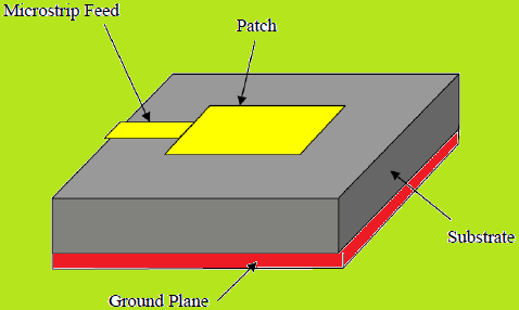
The operating frequency of microstrip antennas usually ranges from 1 to 50 GHz [6][7]. The following figure shows the block diagram of basic microstrip patch antenna system.
2. Quarter wave Transformer
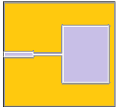
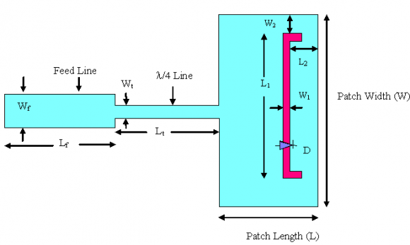
It is quarter wavelength section of a transmission line. It is used to match the impedance between antenna and main transmission feed-line. It is not hard to construct the quarter wave line sections at low values of impedances [8][9][10]. It has an impedance of 70 ohms, which provides exact match to the impedances b/w strip line and the patch antenna elements.
3. III.
4. Design Parameters for C-Band Systems
We start with the microstrip patch antenna by calculating the length and width of a rectangular microstrip antenna for resonance at 4.8 GHz.
The dielectric material selected for the design is FR-4, which has a dielectric constant of 4.4.
5. ? Height of Dielectric Substrate (h):
For the microstrip patch antenna, the height of the dielectric substrate is selected as 1.60 mm. Hence, the essential parameters for the design are:
Resonating frequency, f r = 4.8 GHz..
Permittivity of substrate, ? r = 4.4. Height h of substrate, h = 1.60 mm. Substrate used, FR-4.
IV.
6. Design Equations
Due to fringing effects, electrically patch of antenna looks larger than physical specifications. Enlargement on 'L' is given by [11][12]:
1 1 0.412( 0.3)( 0.264) / ( 0.258)( 0.8) reff reff L Wh Wh ? ? ? ? ? ? ? = + + ? + ? ?Here, effective relative permittivity is as follows:
1 1 1 2 2 1 12 r r reff hW ? ? ? ? + ? = + + -(2)This is related to the ratio of h/W. The larger the h/W, the smaller is the effective permittivity. The effective length of the patch is given by:
2 eff L L L = + ? -(3)The resonance frequency or the TM10 mode is given by:
1 1 2 2( 2 ) r eff reff o o reff o o f L L L ? ? µ ? ? µ = = + ? -(4)Optimized width for efficient radiator is as follows:
1 2 1 2 r r o W f ? ? = + -(5)The reflection coefficient and VSWR can be related through the following formula as:
???????? = 1+|Ð?"| 1?|Ð?"| -(6)The value of reflection coefficient is given by:
Ð?" = (Z L -Z 0 )/(Z L +Z 0 ) -(7)The return loss should be a large negative number as possible. It is defined empirically through following:-
?????? = ?20 log 10 (|Ð?"|) = ?20log 10 ? Z a ?Z o Z a +Z o ? -(8)The impedance bandwidth is inversely proportional to quality factor of an antenna and is given by:-
1 VSWR BW Q VSWR ? = -(9)The bandwidth of an antenna is given by:-
???? = ? 2(ð??"ð??" ?? ?ð??"ð??" ?? ) ð??"ð??" ?? +ð??"ð??" ?? × 100%(Bandwidth < 100 %) or,
???? = ? ð??"ð??" ?? ð??"ð??" ?? ? 1 -(10)(Bandwidth > 100 %) Mathematically, directivity (dimensionless) can be written as:
( ) ( ) ( ) ( ), 4 , 4 , , n t UU U D U P Ud ? ? ? ? ? ? ? ? ? ? = = = ? ?? ? -(11)V.
7. Design Procedure
If the substrate parameters (? r & h) & operatinal frequency (f r ) are known, then we can easily find out patch array dimensions, using above simplified equations and by following the below design procedure:
Step 1: Width Calculation:
Use the above equation to find the patch width W. by substituting the value of f = 4.8 GHz and permittivity as 4.4, the width of the antenna patch comes out to be as 19 mm.
Step 2: Calculation of the effective permittivity: By using the above mentioned equations & putting the value of permittivity as 4.4, width as 19 and height as 1.6 mm, the effective value of dielectric constant is obtained as 3.8985.
8. Step 3: Computation of the extension of length:
The value of extended length comes out to be as 0.7277 mm by using the aforesaid equations [13][14].
Step 4: Determine the actual length 'L': Solving the following equation for 'L' which is given by:
1 2 2 r reff o o L L f ? ? µ = ? ?(12)- Here, difference in length comes out to be 0.7277 mm. The actual length of the patch is obtained as 14.37 mm, while its width comes out to be 19 mm (W/L < 2). The effective value of permittivity of FR-4 is obtained as 3.8985.
9. VI.
10. Design of 50 OHMS Feeding-Line
To design a feed line, the ratio of width of feed line to height of substrate must be less than 2. Their ratio is given by the following relation:
W/d = {8.e A /(e 2A -2)} < 2 - (13)So, A = {(Z 0 )/60}[(1+ ? r )/2] 1/2 + [(-1+ ? r )(.23+.11/ ? r )/(1+ ? r )]Here, the thickness (d) of the substrate is 1.60 mm, ?r is 4.4, length (l) of the feed line is assumed as 07 mm and input impedance of feed line is 50 ohms. The value of constant 'A' is calculated as 1.5297 and that of ?eff (effective) is obtained as 3.8985. Also, w/d is less than 2. So, the width of both the feeding lines comes out to be 3.05 mm. Therefore, W = 3.05 mm and L = 7 mm.
11. VII.
12. Design of Quarter-Wave Transformer
The input resistance to patch is denoted by R in & is given by: R in = (120/2* width of patch)*(c/f)*(? eff ) -1/2 -(14)
From the above equation, the input resistance is obtained as 100 ohms, by putting effective permittivity as 3.8985, frequency as 4.8 GHz and patch width as 19 mm. Therefore, the equivalent resistance is given by [15][16]:
Z q = (50*R in ) 1/2 -(15)So, the equivalent resistance comes out to be 70 ohms. The value of 'A' is obtained as 2.07, by putting permittivity as 4.4 and Z q as 70 ohms. Also, the transformer's width is obtained as 1.656 mm. The length of the transformer is given by the following relation:
L = (1/4)*(? eff ) -1/2 *(wavelength of EM wave) -(16)For a height of 1.6 mm and transformer width of 1.656 mm, the value of effective permittivity comes out to be as 3.18. The parametric values of transformer are obtained as: L = 8.76 mm, W = 1.66 mm, R in = 100 ohms & Z q (equivalent) = 70 ohms.
13. VIII.
14. Mathematical Model Ling
The expression for the effective permittivity is given by the following relation:
0.5 1 1 12 1 2 2 r r eff h W ? ? ? ? + ? ? ? = + + ? ? ? ? -(17)Where, h = Height of dielectric substrate, & W = Width of the patch.
The fringing fields along the width are modelled as radiating slots and electrically, patch of the microstrip antenna looks larger as compared to the physical dimensions. The dimensions of patch along with its length are extended on each end by the distance Î?"l, which is given empirically by the following relation:
0.262 0.3 0.412 0.258 0.814 eff eff W h l h W h ? ? ? ? + ? ? + ? ? ? = ? ? ? ? ? ? ? + ? ? ? ?(18)The effective length of the patch L now becomes:
2 2 r eff c L l f ? = ? ?(19)For efficient radiation, the width W is given by: Step 3: To create substrate Block:
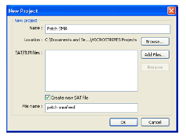
0.5 1 2 2 r r c W f ? ? + ? ? = ? ? ? ?(Create block of substrate plane using the solid block primitive by clicking its tab.
Step 4: To create ground plane Create the ground on dielectric substrate; the ground will be of the same dimensions as the substrate plane.
Step 5: To create Patch:
Create a rectangular patch on top of the dielectric substrate.
Step 6: To create Feed-Line:
Create a 50 ohms feed-line for the patch antenna.
Construct the geometry of the patch antenna. The next step is to describe the electromagnetic parameters of the model.
Step 8: To define material parameters:
Define the materials used in the design and attach them to the geometrical bodies created in the previous section.
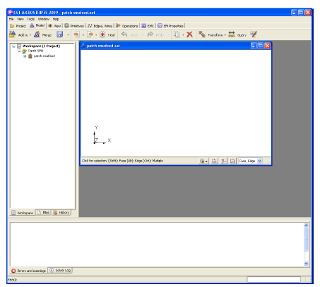
Step 9: Result Analysis: ? Analyze the model and display the results in the CST MICROSTRIPES window. ? The results for the "return loss v/s frequency" will automatically be displayed.
Step 7: To set electromagnetic parameters: