1. Transformer Protection using PlC and GSM Technology
Introduction ow day's protection of equipments in power system is a very important aspect. The power system equipments are valuable and important for well operation of power system network. A Transformer is such equipment which is one of the most important machines in the power system network. High reliability is must for a transformer even in adverse condition. For this condition PLC automation is used; various types of faults in a transformer can be detected and rectified. The Power system without a transformer is like a human without heart. So the protection of a transformer is of utmost importance. The Relays here are provided for sensing the fault current and provide the protection to the transformer. The user gets a message in the form of a SMS (short service message) with the help of a GSM module interfaced with a PLC.
2. II. Fault Detection in Transformer a) Under Voltage
The under voltage fault is when the voltage value gets below some percentage of the rated value according to the countries electrical standards. Here in India according to IES the rated permissible voltage is as below ? Above 33kV (-) 12.5% to (+) 10%. ? Up to 33kV (-) 9.0% to (+) 6.0%. ? Low voltage (-) 6.0% to (+) 6.0%
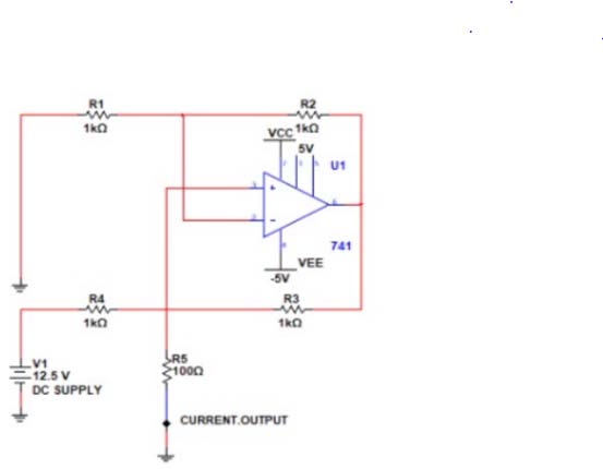
The faults can be detected using a voltage sensor or a Potential Transformer. So there is a PT connected to a transformer which steps down the voltage. The voltage is then converted to current through V to I converter and then that current is fed to the PLC. The fed current from the V to I converter will be in the range of 4 to 20 MA.
3. b) Over Voltage
The over voltage fault occurs when the value of voltage exceeds some percentage of the rated value as per the countries electrical standards. In India the electrical standards are as shown above.
Due to sudden disconnection of a large load there is possibility of an increase in voltage. Over voltage in the power system generally causes an increase in stress on the insulation of transformer. Here also PT is used which steps down the voltage. Then the voltage is converted to current using V to I converter. This output current from the V to I converter will be in the range of 4 to 20 MA. c) Over Load/ Over Current Over loading is when over current stats flowing on the secondary side of a transformer. The over load or the over current fault occurs when the current in a transformer exceeds its rated current value. Sometimes due to sudden increase in the load more amount of current gets drawn which is higher than the rated current of our transformer. This condition occurs for a very short time as it is a harmful condition for our transformer and is tripped rapidly. So a CT is used which steps down the current and gives input to our PLC in the range of 4 to 20 MA.
4. d) Temperature
When the temperature inside transformer goes above a rated value it is harmful for the windings. The transformer rated on a 24-hour average ambient temperature of 30°C (86°F). Increase in over current and over voltage leads to increase in the temperature of transformer oil which might weaken the breakdown strength of the winding insulation. This temperature increase can be a result of high current, seasonal change, region of operation. Due to high temperature the insulation can break down and following which a short circuit may occur. This fault can be detected using a temperature transducer.
5. e) Phase to Phase Fault
This type of fault occurs when one phase gets shorted to the other. This gives rise to high current to flow compared to the earth fault current.
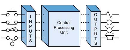
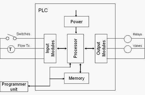
6. II. Plc (programmable Logic
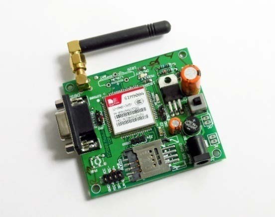
Controllers) The GSM sends data in the form of SMS (short message service) message to indicate if any fault occurs or if there is any abnormal condition. The GSM module can also send the user the status and alarms. This GSM Modem can accept any GSM network operator SIM card. Advantage of using this modem will be that you can use its RS232 port to communicate and develop embedded applications.
7. IV. GSW
Applications like SMS Control, data transfer, remote control and logging can be developed easily. The modem can either be connected to PC serial port directly or to any microcontroller or PLC. It can be used to send and receive SMS .Components that are needed to interface the GSM with PLC are RS485 to RS232 converter, RS232 cable, SMPS for PLC power supply, GSM module and PLC.
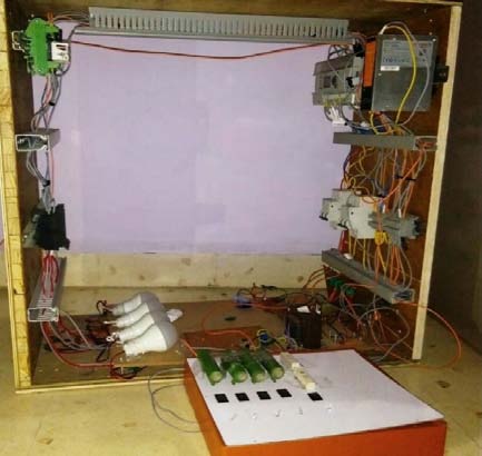
8. V. DESIGN OF PLC BASED TRANSFORMER PROTECTION
9. F
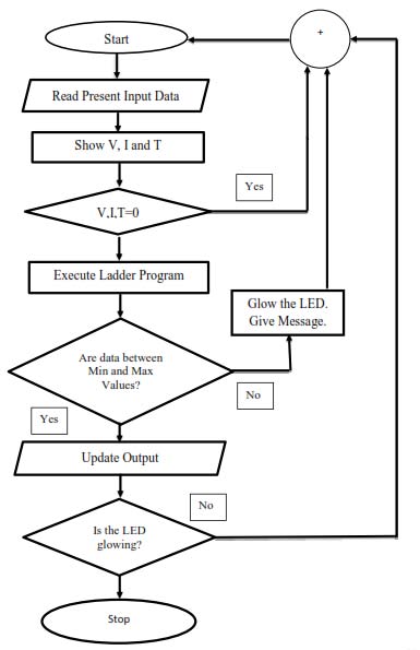
When the parameters being tested are in rated condition the the PLC will trigger the healthy output signal to the healthy system indicated LED. During fault the parameters V and I will exceed its lower or upper limit with respect to the PLC's fed reference input. During this condition the PLC will immediately trigger the respective trigger pulse.
10. g) PLC Output
During the time of fault the PLC triggers signal pulse to the trip circuit and alarm circuit. Here there is a LED as an indication for the faulty condition. Each colour LED states different type of fault. Further the PLC sends the command to the GSM module fed with a program to send the fault message.
11. h) GSM
The GSM when gets a command from the PLC about the occurred fault and the nature of fault. Further according to the programmed GSM and fed message about the respective fault the message of the fault is send to the user. Thus the fault message is displayed on the users mobile phone.
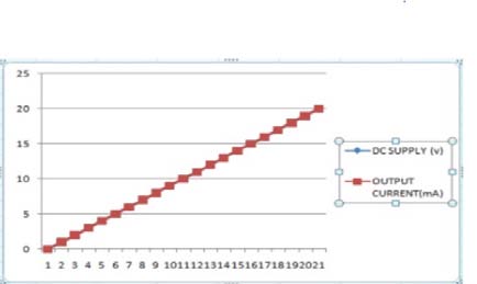
12. VI.
13. Characteristic Data
14. Conclusion
In this proposed system we have designed a protection system of transformer based on PLC that is used to observe and control the current, voltage and temperature of a power and distribution transformer on both the primary and secondary sides. The proposed PLC system which has been designed to monitor the transformer's required parameter. It continuously monitors these parameters throughout its operation. When the PLC identify any change in the level of voltage, current or temperature values exceeding the upper or lower limit of rating respectively, the transformer has been made shut-down in order to protect from damages with the help of relays in the system. The system not only controls the transformer in the substation by shutting it down, but also displays the values throughout the process for users on HMI screen of PLC. This demand that the proposed design of the PLC system makes the transformer more robust against the adverse issues which makes the voltage, current or temperature to peak. Hence the distribution is made more secure, reliable and highly efficient by means of the proposed system. From this model we protect the distribution or power transformer from the adverse condition hence total life span of the transformer increase up to some extent.