1. I. Introduction
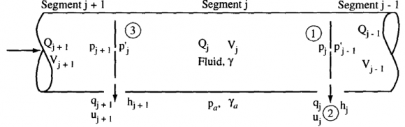
ydraulic pipeline systems range from the very simple ones to very large and quite complex ones. A system may consist of a number of sub-networks separated by differing energy lines or pressure values. In order to study the Head loss and Energy loss across a pipe flow and to design Hydraulic pipelines individually or in manifold configuration, the following notations were used. The notations are shown in figure 1 for a computational sequence flow design. The manifold ports and barrel segments are numbered from the downstream end toward the upstream supply head or reservoir, with each port and segment number that is up stream of it denoted by j, which will also be used as a subscript on the other variables to indicate their location. Other variables are Q= discharge in the barrel segment, V= mean velocity in the barrel segment, A= cross-sectional area of the barrel segment, D= diameter of the barrel segment, q= discharge from a port, u= mean velocity through a port, a= cross-sectional area of a port, and d= diameter of a port. The fluid being conveyed has a unit weight of ?. The hydraulic model of flow in a pipe Has a discrete jump in pressure across a port; just upstream of port j the internal pressure is P J , and the pressure immediate downstream of the next port is p j .
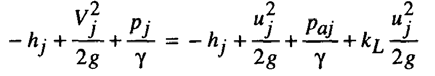
We write an energy equation from a point inside the main control volume, point 1 to another rinstance in the port efflux stream, point 2:
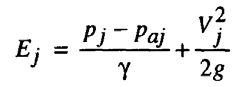
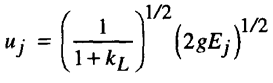
In the above equation, K L is the port head loss coefficient. If we define an energy parameter E at port J as Then the fluid exit velocity through the port is given by What makes the hydraulic system of aircraft more complicated is the fact that there is continuous transfer of forces and momentum between the pipe structure and hydraulic fluid (at high pressure of about 3000 Psi). Excitation caused by high frequency pulsation of flow coupled with vibration from equipment around viz Gas Turbine, gear mechanisms, etc. can lead to fatigue failure of these pipes.
2. II. CFD Analysis of Pipelines
The CFD analysis of commonly occurring defects in hydraulic pipelines carrying high pressure hydraulic fluid follows a sequence of technical processes along with scientific data analysis. The processes are explained in brief.
3. a) Preliminary study phase
It is necessary to study the physical problem analytically prior approaching the modeling and simulation phase. A proper preliminary study of the physical problem will help us individuate the assumptions and simplifications that are acceptable. In our case simplification lead to reduction in geometric complexity while allowing the thermal transfer equations. Hence this phase is fundamental to an accurate simulation result.
4. c) Meshing
Mesher plays an essential role in providing simulation related information to our model. During this process the model was divided into regions and surfaces. For the mesh to be usable all the boundaries relevant to the physical problem must be identified. These features will be used during the simulation setup phase to define fluids, solids and boundary conditions properties. The accuracy of the simulation result is dependent on the mesh geometry to a great extent. This was evident during our various iterations and subsequently an Optimal.
5. d) Solver for Simulation
During this phase we define the properties of all the fluids, solids and boundaries in fine detail. The choice of solver that is most suitable for the particular case is also decided in this phase viz. incompressible flow, compressible flow, steady solution, dynamic solution heat transfer and so on. We chose SOLID 185 and FLUID 142 for representing our Material of pipeline and Hydraulic Fluid respectively. We have defined the initial conditions as encountered by a hydraulic pipeline in an aircraft system (these are the values that the variables take at the beginning of simulation). The solution is accepted through verification and validation.
6. e) Data visualization and post processing
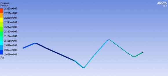
Post processing data visualization is the most important human interface to understand the analysis. The incremental behaviour of various parameters associated to our analysis like speed, pressure and density need to be visualized. The data compilation and visualization should be such that the value of particular physical parameter can be extracted or derived as per requirement for further detail analysis.
7. III.
8. Experiment
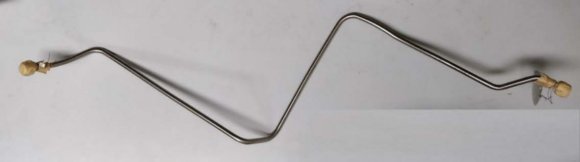
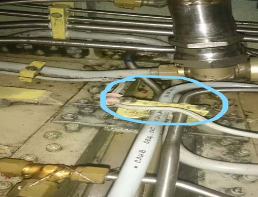
In order to carry out the study, a particular hydraulic pipe line, of one of the high-speed aircrafts, which had shown signs of frequently failure was considered. To carry out CFD analysis and stress analysis, we collected various parameters required for initialization as per Aircraft Manual. These parameters are required to be fed exactly as per dimension during mathematical modeling of the pipeline to obtain an accurate and stable solution. The parameters are: The figure given below is the photograph of a frequently failing hydraulic pipeline on the pressure side. This hydraulic pipe supplys required hydraulic pressure to the actuator of flying controls of an aircraft.
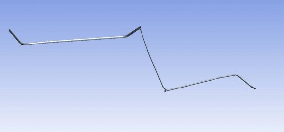
9. b) Geometric modelling
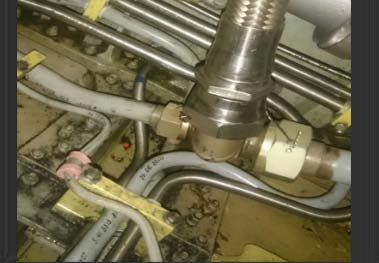
Geometrical models can be either 3D or 2D. It has to be an optimal choice so that it is easy to pass the data to the mesher software. iii. Kinematic viscosity --25mm 2 /s iv. Type --mixture of polysiloxane fluid and organic ether with addition of anti wear additive + antioxidant It is a known fact that the hydraulic pipelines are to be routed complexly inside an aircraft equipment bay due to space constraint. Also, the various components of the Hydraulic system including actuators are located at distant positions, depending on their utility and design criteria, which causes sufficient length of pipelines to be laid out that further requires support and clamping to hard points on the fuselage. In our case the specific pipeline was clamped to 03 hard points at the bulkhead at mid fuselage. The defects reported by an MRO were of chaffing, crack and dent. On scrutiny it was discovered that the root cause would be excessive stress and vibration and dent being attributed to the process of bending or routing. In order to analyse the vibration related stress and provide a solution, three cases were considered:
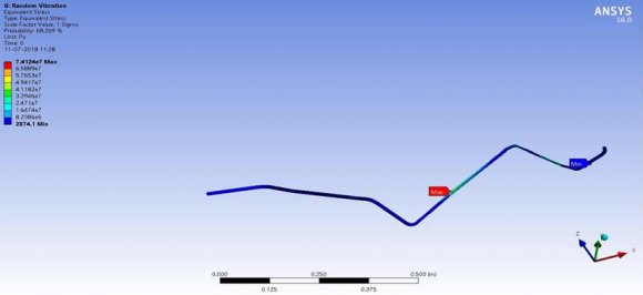
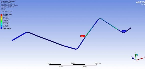
10. VI. Results
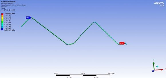
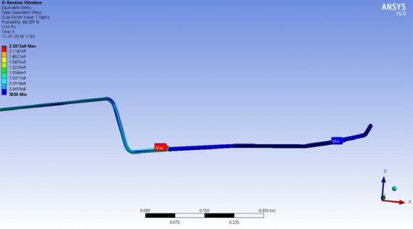
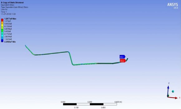
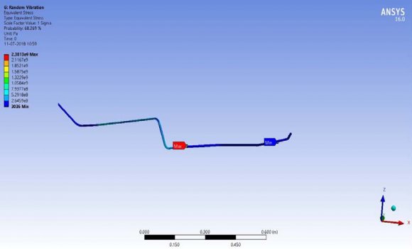
After the simulation with help of ANSYS and both CFX, FLUENT Solver, the equivalent stress distribution through the length of the pipeline was scrutinized for abnormality and the location of maximum stresses were identified. The simulation data are tabulated below in Table 2.
11. VII. Analysis Report
Below mentioned are few of the common factors that can affect the health of Hydraulic pipelines which carry high pressure hydraulic fluid. The Hydraulic system plays an extremely vital role in aircraft operation. These common mistakes may be avoided for deterioration of hydraulic pipelines and any further catastrophic failure.
12. a) Manufacturing Process and Handling
Pipes are required to be casted as per routing. No further bending should be carried out by using primitive methods like hammering. It has been proved through various experiments that bending of pipeline causes severe stress concentration at the point of bend that may cause crack initiation (Griffith energy criteria) It has been observed that external force is applied in order to fix pipeline into the system/ routing in the equipment bay. This external force is applied either by bending the pipeline or by hammering. This leads to increase in residual stress inside the body which reduces strength of material. Finally, it leads to crack initiation and propagation.
When external forces or hand pressure is applied on the pipeline to fix the pipeline then it reduces the distance between the pipelines. Sometimes pipelines come in contact with each other. It leads to the chaffing of material. Pipelines rub against each other, causing erosion of the surface and eventual failure. The transfer of vibration and other dynamic loads can cause deterioration of pipelines. A pipe support or pipe hanger is a designed element that transfers the load from a pipe to the supporting structures. The four main functions of a pipe support are to anchor, guide, absorb shock, and support a specified load. Pipe supports used in high or low temperature applications may contain insulation materials. The overall design configuration of a pipe support assembly is dependent on the dynamic loading factor and operating conditions.
There is no thumb rule for number of supports to be used on particular pipeline. Generally, support is placed on the longer and straight pipelines. So, an attempt was made to observe stresses by increasing no. of supports. It was found out that stress could be reduced by 32 times, by increasing the support points by 30% while keeping the material of pipeline same.
13. iii. Changing Material of Pipeline
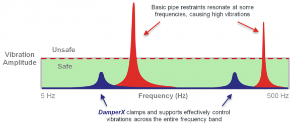
Pipeline is subjected to high pressure (210 kg/cm 2 ) and vibration. So, Material strength was also considered as a reason of failure. Titanium was considered as a replacement of steel. It was found that with 4 no. of clamps, stresses in steel pipeline are 1.4 times titanium (as compared to 32 times decrease in equivalent stress due to an additional support clamp). It proves that material performance is satisfactory. So, there is no need to change material from steel to titanium. The use of Hydraulics for operation of various components of an aircraft viz Control surfaces, Undercarriage etc is inevitable. With increase in AUW, the hydraulic system gets more and more bulky and complexity of pipeline system also increases. The flying envelope and max speed of the aircraft also decides the aerodynamic forces on various Control surfaces which in turn decide the robustness of the Hydraulic system. As these dynamic forces increase, the system requirement also becomes more stringent. We used CFX and FLUENT Solver to simulate the flow through a specific hydraulic pipeline which has a history of failing 3 Mpa to 74.12 Mpa. iv. Changing the material from steel to titanium didn't have any profound effect on reduction of Equivalent stress in pipeline. However, stress reduced from 74.12 Mpa to 51.62 Mpa (with 4 Supports). v. In order to reduce the vibration stress and reduce the chance of failure, an additional4 th support clamp is proposed for the specific hydraulic pipeline as shown below. The hydraulic pipelines are subjected to higher dynamic stresses due to combinatory force of high pressure, temperature and vibration. Hence, clamping of these pipelines using active vibration dampers on main frame or bulkhead of aircraft should be explored. In order to avoid chaffing between pipelines, better pipeline routing may also be explored during design phase.
14. VIII. Conclusion


| S. no. | Parameters | Part no. y.yy.yyyy.yy |
| 1 | Internal diameter | 8.22mm |
| 2 | External diameter | 10.22mm |
| 3 | Flow rate | 185 l/min |
| 4 | Length of pipeline | 52" |
| 5 | Pressure through pipeline | 210 kg/cm 2 |
| Test | Steel with 3 support | Titanium with 3 support | Steel with 4 support | Titanium with 4 support |
| Static structural analysis (stress) | 1220.4Mpa | 1207 Mpa | 1107.5 Mpa | 1088 Mpa |
| Random vibration analysis(stress) | 2381.3 Mpa | 2381 Mpa | 74.12 Mpa | 51.62 Mpa |