1.
Abstract-Story Drift is defined as the difference in lateral deflection between two adjacent stories. Lateral deflection and drift have three effects on a structure; the movement can affect the structural elements (such as beams and columns); the movements can affect non-structural elements (such as the windows and cladding); and the movements can affect adjacent structures. Without proper consideration during the design process, large deflections and drifts can have adverse effects on structural elements, nonstructural elements, and adjacent structures. Drift problem as the horizontal displacement of all tall buildings is one of the most serious issues in tall building design, relating to the dynamic characteristics of the building during earthquakes and strong winds. Drift shall be caused by the accumulated deformations of each member, such as a beam, column and shear wall. lateral forces due to wind or seismic loading must be considered for tall building design along with gravity forces vertical loads. Tall and slender buildings are strongly wind sensitive and wind forces are applied to the exposed surfaces of the building, whereas seismic forces are inertial (body forces), which result from the distortion of the ground and the inertial resistance of the building. These forces cause horizontal deflection is the predicted movement of a structure under lateral loads and The structural prototype is prepared and lots of data is been collected from the prototype. All the aspects such as safety of structure in shear, moment and in story drift have been collected. Main problems that would be arising due to earthquake in the structure are story drift and deflection of the building due to its large height and also torsion and others, so if the structure is proved to be safe in all the above mentioned problems than the structure would be safe in all cases in respect earthquake. Shear Wall is A Structural Element Used to Resist Lateral, Horizontal, Shear Forces Parallel to the Plane of the Wall By: Cantilever Action For Slender Walls Where The Bending Deformation Is Dominant. Truss Action For Squat/Short Walls Where The Shear Deformation is Dominant. Shear walls are analyzed to the provide necessary lateral strength to resist horizontal forces. Shear walls are strong enough, to transfer these horizontal forces to the next element in the load path below them. The seismic motion that reaches a structure on the surface of the earth is influenced by local soil conditions. The subsurface soil layers underlying the building foundation may amplify the response of the building to earthquake motions originating in the bedrock. Three types soil are considered here: Hard soil ,Medium soil, soft soil. In the present work thirty story buildings with C Shape, Box shape, E Shape, I shape and Plus shape RC Shear wall at the center in Concrete Frame Structure with fixed support conditions under different type of soil condition for earthquake zone V as per IS 1893 (part 1) : 2002 in India are analyzed using software ETABS by Dynamic analysis. All the analyses has been carried out as per the Indian Standard code books. This paper aims to Study the effect on the drift (lateral deflection) of the tall buildings due to earthquake loading. In dynamic analysis; Response Spectrum method is used.
Study the Impact of the Drift (Lateral Deflection) of the Tall Buildings Due to Seismic Load in Concrete Frame Structures with Different Type of RC Shear Walls Mahdi Hosseini ? & N.V. Ramana Rao ? a) Earthquake Load arthquake forces experienced by a building result from ground motions (accelerations) which are also fluctuating or dynamic in nature, in fact they reverse direction some what chaotically. The magnitude of an earthquake force depends on the magnitude of an earthquake, distance from the earthquake source(epicenter), local ground conditions that may amplify ground shaking (or dampen it), the weight(or mass) of the structure, and the type of structural system and its ability to with stand aI busive cyclic loading. In theory and practice, the lateral force that a building experiences from an earthquake increases in direct proportion with the acceleration of ground motion at the building site and the mass of the building (i.e., a doubling in ground motion acceleration or building mass will double the load).This theory rests on the simplicity and validity of Newton's law of physics: F = m x a, where 'F' represents force, 'm' represents mass or weight, and 'a' represents acceleration. For example, as a car accelerates forward, a force is imparted to the
2. INTRODUCTION
3. Global
4. Journal of Researches in Engineering ( ) Volume XVIII Issue I Version I
Story drift, which is defined here as the relative horizontal displacement of two adjacent floors, can form the starting point for assessment of damage to nonstructural components such as facades and interior partitions. However, it is more informative in high-rise buildings to assess these relative movements in each story as components due to:
A) Rigid body displacement. b) Racking (shear) deformation.Rigid body displacement is associated with the 'rotation' of the building as a whole at upper levels due to vertical deformations in the columns below, and induces no damage.
Racking hear deformation is a measure of the angular in-plane deformation of a wall or cladding panel. This will in general vary at different positions on a floor, and may exceed the story drift ratio in some locations, (e.g. partition panels spanning between a core and a perimeter column). Inelastic element deformations form the basis for assessment of structural damage and potential for structural collapse. Assessments are generally performed one component at a time by comparing deformation demands with permissible values (e.g., maximum plastic hinge rotations) that are based on structural details (e.g. tie spacing in concrete elements) and co-existing member forces.
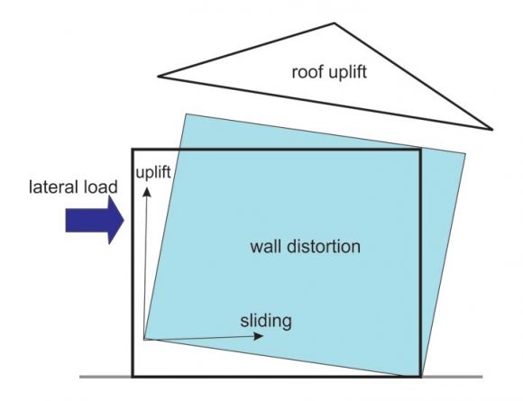
When a building is subjected to wind or earthquake load, various types of failure must be prevented:
The first three types of failure are schematically shown in the Figure . 1 Clearly, the entire system must be tied together to prevent building collapse or significant deformation.
5. II.
6. METHODOLOGY
Earthquake motion causes vibration of the structure leading to inertia forces. Thus a structure must be able to safely transmit the horizontal and the vertical inertia forces generated in the super structure through the foundation to the ground. Hence, for most of the ordinary structures, earthquake-resistant design requires ensuring that the structure has adequate lateral load carrying capacity. Seismic codes will guide a designer to safely design the structure for its intended purpose. Seismic codes are unique to a particular region or country. In India, IS 1893(Part1): 2002is the main code that provides outline for calculating seismic design force. This force depends on the mass and seismic coefficient of the structure and the latter in turn depends on properties like seismic zone in which structure lies, importance of the structure, its stiffness, the soil on which it rests, and its ductility. IS 1893 (Part 1): 2002deals with assessment of seismic loads on various structures and buildings. Whole the code centers on the calculation of base shear and its distribution over height.
The analysis can be performed on the basis of the external action, the behavior of the structure or structural materials, and the type of structural model selected. Depending on the height of the structure and zone to which it belongs, type of analysis is performed. In all the methods of analyzing multi-storey buildings recommended in the code, the structure is treated as discrete system having concentrated masses at floor levels, which include half that of columns and walls above and below the floor. In addition, appropriate amount of live load at this floor is also lumped with it. (this force is equivalent to the weight of the driver multiplied by the acceleration or rate of change in speed of the car). As the brake is applied, the car is decelerated and a force is imparted to the driver by the seatbelt to push him back toward the seat. Similarly, as the ground accelerates back and forth during an earthquake, it imparts back-and-forth (cyclic) forces to a building through its foundation which is forced to move to the ground. One can imagine a very light structure such as a fabric tent that will be undamaged in almost any earthquake but it will not survive high wind. The reason is the low mass (weight) of the tent. Therefore, residential buildings generally perform reasonably well in earthquakes, but are more vulnerable in high-wind load prone areas. Regardless, the proper amount of bracing is required in both cases.
driver through the seat to push him forward with the car
? Slipping off the foundation (sliding)
? Overturning and uplift (anchorage failure)
? Shear distortion (drift or racking deflection)
? Collapse (excessive racking deflection)
Quite a few methods are available for the earthquake analysis of buildings; two of them are presented here: 1-Equivalent Static Lateral Force Method (pseudo static method). 2-Dynamic analysis.
7. a) Dynamic analysis
Dynamic analysis shall be performed to obtain the design seismic force, and its distribution in different levels along the height of the building, and in the various lateral load resisting element, for the following buildings: Regular buildings: Those greater than 40m in height in zones IV and V, those greater than 90m in height in zone II and III. Irregular buildings: All framed buildings higher than 12m in zones IV and V, and those greater than 40m in height in zones II and III.
The analysis of model for dynamic analysis of buildings with unusual configuration should be such that it adequately models the types of irregularities present in the building configuration. Buildings with plan irregularities, as defined in Table 4 of IS code: 1893-2002 cannot be modeled for dynamic analysis.
Dynamic analysis may be performed either by the TIME HISTORY METHOD or by the RESPONSE SPECTRUM METHOD
8. b) Time History Method
The usage of this method shall be on an appropriate ground motion and shall be performed using accepted principles of dynamics. In this method, the mathematical model of the building is subjected to accelerations from earthquake records that represent the expected earthquake at the base of the structure.
9. c) Response Spectrum Method
The word spectrum in engineering conveys the idea that the response of buildings having a broad range of periods is summarized in a single graph. This method shall be performed using the design spectrum specified in code or by a site-specific design spectrum for a structure prepared at a project site. The values of damping for building may be taken as 2 and 5 percent of the critical, for the purposes of dynamic of steel and reinforce concrete buildings, respectively. For most buildings, inelastic response can be expected to occur during a major earthquake, implying that an inelastic analysis is more proper for design. However, in spite of the availability of nonlinear inelastic programs, they are not used in typical design practice because:
1-Their proper use requires knowledge of their inner workings and theories. design criteria, and 2-Result produced are difficult to interpret and apply to traditional design criteria, and 3-The necessary computations are expensive. Therefore, analysis in practice typically use linear elastic procedures based on the response spectrum method. The response spectrum analysis is the preferred method because it is easier to use.
10. d) Response Spectrum Analysis
This method is also known as modal method or mode superposition method. It is based on the idea that the response of a building is the superposition of the responses of individual modes of vibration, each mode responding with its own particular deformed shape, its own frequency, and with its own modal damping.
According to IS-1893(Part-l): 2002, high rise and irregular buildings must be analyzed by response spectrum method using design spectra shown in Figure 4.1. There are significant computational advantages using response spectra method of seismic analysis for prediction of displacements and member forces in structural systems. The method involves only the calculation of the maximum values of the displacements and member forces in each mode using smooth spectra that are the average of several earthquake motions. Sufficient modes to capture such that at least 90% of the participating mass of the building (in each of two orthogonal principle horizontal directions) have to be considered for the analysis. The analysis is performed to determine the base shear for each mode using given building characteristics and ground motion spectra. And then the storey forces, accelerations, and displacements are calculated for each mode, and are combined statistically using the SRSS combination. However, in this method, the design base shear (VB) shall be compared with a base shear (Vb) calculated using a fundamental period T. If V_B is less than V_b response quantities are (for example member forces, displacements, storey forces, storey shears and base reactions) multiplied by VB/V_b Response spectrum method of analysis shall be performed using design spectrum. In case design spectrum is specifically prepared for a structure at a particular project site, the same may be used for design at the discretion of the project authorities. Figure 4.1 shows the proposed 5% spectra for rocky and soils sites.
11. e) Seismic Analysis Procedure as per the Code
When a structure is subjected to earthquake, it responds by vibrating. An example force can be resolved into three mutually perpendicular directionstwo horizontal directions (X and Y directions) and the vertical direction (Z). This motion causes the structure to vibrate or shake in all three directions; the predominant time's gravity in the vertical direction. Because of the inherent factor used in the design specifications, most structures tend to be adequately protected against vertical shaking. Vertical acceleration should also be considered in structures with large spans those in which stability for design, or for overall stability analysis of structures. The basic intent of design theory for earthquake resistant structures is that buildings should be able to resist minor earthquakes without damage, resist moderate earthquakes without structural damage but with some non-structural damage. To avoid collapse during a major earthquake, Members must be ductile enough to absorb and dissipate energy by post elastic deformation. Redundancy in the structural system permits redistribution of internal forces in the event of the failure of key elements. When the primary element or system yields or fails, the lateral force can be redistributed to a secondary system to prevent progressive failure.
IS 1893 (part-1) Code recommends that detailed dynamic analysis, or pseudo static analysis should be carries out depending on the importance of the problems.
IS 1893 (part-1) Recommends use of model analysis using response spectrum method and equivalent lateral force method for building of height less than 40m in all seismic zones as safe., but practically there may be the building which are more than 40m in height. So there exist so many problems due to the increase in height of the structure.
The earthquake resistant structures are constructed using IS 1893 part-1 and there are some assumptions to be made in the design according to the codal provisions and these assumptions account to one of the uncertainties that occur in the design starting from mix design to workmanship and many other.
The following assumptions shall be made in the earthquake resistant design of structures:
Earthquake causes impulsive ground motions, which are complex and irregular in character, changing in period and amplitude each lasting for a small duration. Therefore, resonance of the type as visualized under steady-state sinusoidal excitations will not occur as it would need time to buildup such amplitudes.
12. III.
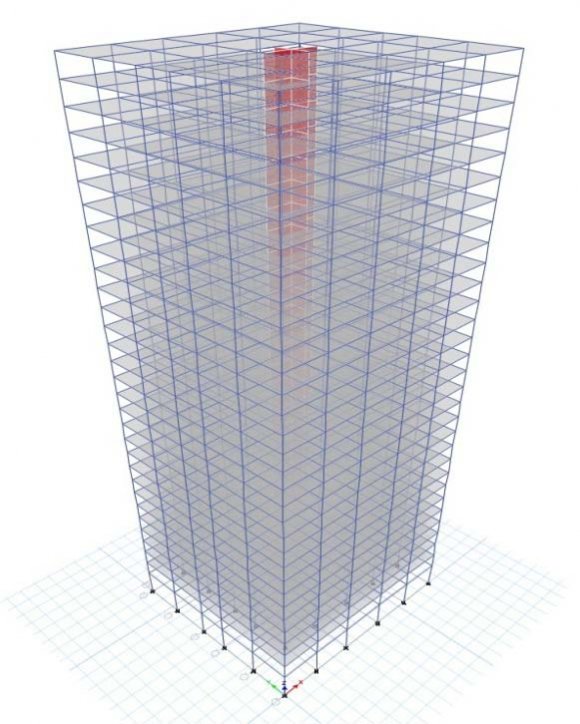
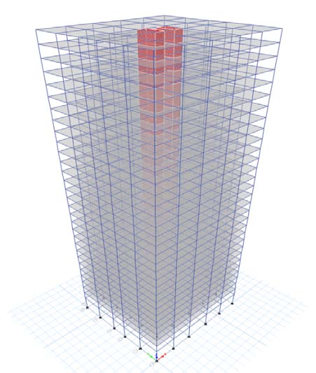
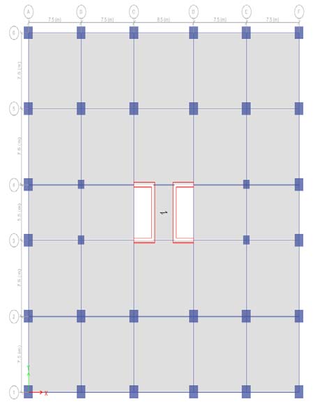
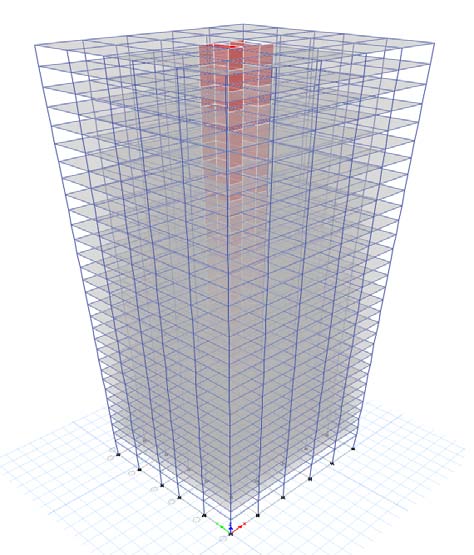
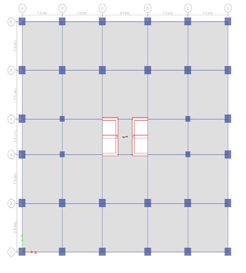
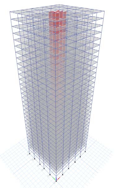
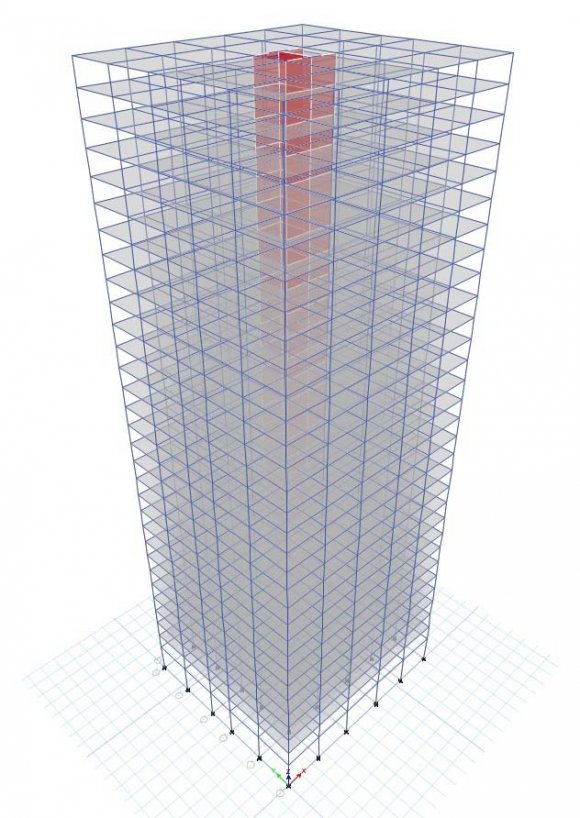
13. MODELING OF BUILDING a) Details of The Building
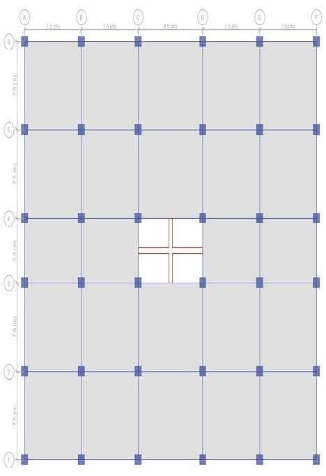
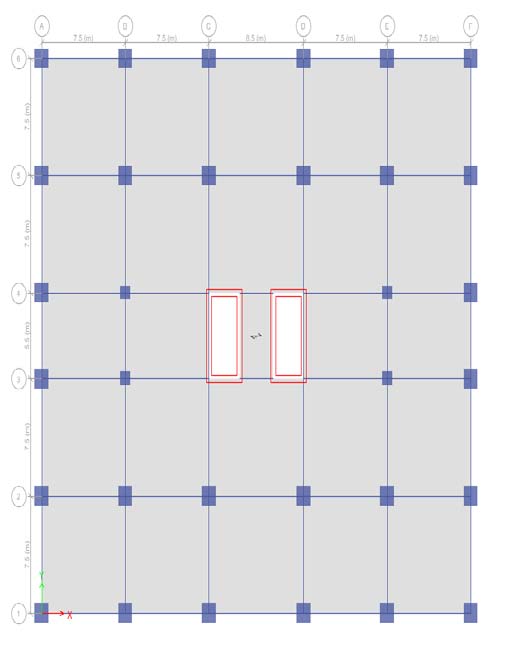
A symmetrical building of plan 38.5m X 35.5m located with location in zone V, India is considered. Four bays of length 7.5m& one bays of length 8.5m along X -direction and Four bays of length 7.5m& one bays of length 5.5m along Y -direction are provided. Shear Wall is provided at the center core of building model.
14. b) Load Combinations
As per IS 1893 (Part 1): 2002 Clause no. 6.3.1.2, the following load cases have to be considered for analysis:
1.5 (DL + IL) 1.2 (DL + IL ± EL) 1.5 (DL ± EL) 0.9 DL ± 1.5 EL Earthquake load must be considered for +X, -X, +Y and -Y directions.
15. RESULTS AND DISCUSSIONS
16. Discussion on Results
When a structure is subjected to earthquake, it responds by vibrating. An example force can be resolved into three mutually perpendicular directionstwo horizontal directions (X and Y directions) and the vertical direction (Z). This motion causes the structure to vibrate or shake in all three directions; the predominant direction of shaking is horizontal. All the structures are primarily designed for gravity loads-force equal to mass time's gravity in the vertical direction. Because of the inherent factor used in the design specifications, most structures tend to be adequately protected against vertical shaking. Vertical acceleration should also be considered in structures with large spans those in which stability for design, or for overall stability analysis of structures. The basic intent of design theory for earthquake resistant structures is that buildings should be able to resist minor earthquakes without damage, resist moderate earthquakes without structural damage but with some non-structural damage. To avoid collapse during a major earthquake, Members must be ductile enough to absorb and dissipate energy by post elastic deformation. Redundancy in the structural system permits redistribution of internal forces in the event of the failure of key elements. When the primary element or system yields or fails, the lateral force can be redistributed to a secondary system to prevent progressive failure.
The structural prototype is prepared and lots of data is been collected from the prototype. All the aspects such as safety of structure in shear, moment and in story drift have been collected. So now to check whether to know whether the structure is safe with established shear walls and all construction of core wall in the center we need to compare the graphical values of structure with the shear wall and a simple rigid frame structure.
The structures are supported on soil, most of the designers do not consider the soil structure interaction and its subsequent effect on structures during an earthquake. When a structure is subjected to an earthquake excitation, it interacts with the foundation and the soil, and thus changes the motion of the ground. This means that the movement of the whole ground-structure system is influenced by the type of soil as well as by the type of structure. Understanding of soil structure interaction will enable the designer to design structures that will behave better during an earthquake.
17. a) Story Drift
The tallness of a structure is relative and cannot be defined in absolute terms either in relation to height or the number of stories. The council of Tall Buildings and Urban Habitat considers building having 9 or more stories as high-rise structures. But, from a structural engineer's point of view the tall structure or multi-storied building can be defined as one that, by virtue of its height, is affected by lateral forces due to wind or earthquake or both to an extent. Lateral loads can develop high stresses, produce sway movement or cause vibration. Therefore, it is very important for the structure to have sufficient strength against vertical loads together with adequate stiffness to resist lateral forces. So lateral forces due to wind or seismic loading must be considered for tall building design along with gravity forces vertical loads. Tall and slender buildings are strongly wind sensitive and wind forces are applied to the exposed surfaces of the building, whereas seismic forces are inertial (body forces), which result from the distortion of the ground and the inertial resistance of the building. These forces cause horizontal deflection is the predicted movement of a structure under lateral loads and story drift is defined as the difference in lateral deflection between two adjacent stories. Lateral deflection and drift have three effects on a structure; the movement can affect the structural elements (such as beams and columns); the movements can affect non-structural elements (such as the windows and cladding); and the movements can affect adjacent structures. Without proper consideration during the design process, large deflections and drifts can have adverse effects on structural elements, nonstructural elements, and adjacent structures.
When the initial sizes of the frame members have been selected, an approximate check on the horizontal drift of the structures can be made. The drift in the non-slender rigid frame is mainly caused by racking. This racking may be considered as comprising two components: the first is due to rotation of the joints, as allowed by the double bending of the girders, while the second is caused by double bending of the columns. If the rigid frame is slender, a contribution to drift caused by the overall bending of the frame, resulting from axial deformations of the columns, may be significant. If the frame has height width ratio less than 4:1, the contribution of overall bending to the total drift at the top of the structure is usually less than 10% of that due to racking. The following method of calculation for drift allows the separate determination of the components attributable to beam bending, and overall cantilever action. Drift problem as the horizontal displacement of all tall buildings is one of the most serious issues in tall building design, relating to the dynamic characteristics of the building during earthquakes and strong winds. Drift shall be caused by the accumulated deformations of each member, such as a beam, column and shear wall. In this study analysis is done with changing structural parameters to observe the effect on the drift (lateral deflection) of the tall building due to both wind and earthquake loading. There are three major types of structures were identified in this study, such as rigid frame, coupled shear wall and wall frame structures.
18. IS 1893 Part 1 Codal Provoisions for Storey Drift Limitations
The storey drift in any storey due to the minimum specified design lateral force, with partial load factor of 1.0, shall not exceed 0.004 times the storey height For the purposes of displacement requirements only, it is permissible to use seismic force obtained from the computed fundamental period (T) of the building without the lower bound limit on design seismic force specified in dynamic analysis.
The result obtained from the analysis models will be discussed and compared as follows: ? The maximum storey drift in X-direction occurred at storey 13 th for structure1 in hard ,medium and soft soil.
? The maximum storey drift in X-direction occurred at storey 12 th for structure 2 in hard ,medium and soft soil. ? The maximum storey drift in X-direction occurred at storey 11 th for structure 3 in hard ,medium and soft soil. ? The maximum storey drift in X-direction occurred at storey 11 th for structure 4 in hard ,medium and soft soil. ? The maximum storey drift in X-direction occurred at storey 14 th for structure 5 in hard ,medium and soft soil.
19. CONCLUSIONS
In this paper, reinforced concrete shear wall buildings were analyzed with the procedures laid out in IS codes. Seismic performance of building model is evaluated. In this study, regular shaped structures have been considered. Estimation of drift was carried out for Dual frame system with shear wall structure. This study indicates that the drift on high rise structures has to be considered as it has a notable magnitude. So every tall structure should include the drift due to earthquake load.
From the above results and discussions, following conclusions can be drawn: 1. Building with box shape Shear Walls provided at the center core showed better performance in term of maximum storey drifts. 2. From result observed that drift is increased as height of building increased and reduced at top floor.
3. From the comparison of story drift values it can be observed that maximum reduction in drift values is obtained when shear walls are provided at center of the building. 4. As per code, the actual drift is less than permissible drift. The parallel arrangement of shear wall in the center core and outer periphery is giving very good result in controlling drift in both the direction. The better performance for all the structures with soft soil because it has low storey drift. 5. Storey drifts are found within the limit ,As per Indian standard, Criteria for earthquake resistant design of structures, IS 1893 (Part 1) : 2002, the story drift in any story due to service load shall not exceed 0.004 times the story height. 6. The moment resisting frame with shear walls are very good in lateral force such as earthquake and wind force. The shear walls provide lateral load distribution by transferring the wind and earthquake loads to the foundation. And also impact on the lateral stiffness of the system and also carries gravity loads. 7. For severe lateral loads caused by wind load and or earthquake load, the reinforced shear wall is obvious. Because, it produces less deflection and less bending moment in connecting beams under lateral loads than all others structural system. 8. Based on the analysis and discussion, shear wall are very much suitable for resisting earthquake induced lateral forces in multistoried structural systems when compared to multistoried structural systems whit out shear walls. They can be made to behave in a ductile manner by adopting proper detailing techniques. 9. ETABS is the advanced software which is used for analysing any kind of building structures. By its fast and accuracy it can easily analyses buildings up to 40 floors. 10. ETABS can analyse any building structure with predetermined load conditions and load combinations for shear walls regarding IS codes. 11. So, for designing of building shear wall structure if we use ETABS software then it analyse the building easily and give the fast results with accurate data.


| Parameters Building | Details |
| Type of frame | Special RC moment resisting frame fixed at the base |
| Building plan | 38.5m X 35.5m |
| Number of storeys | 30 |
| Floor height | 3.5 m |
| Depth of Slab | 225 mm |
| Size of beam | (300 × 600) mm |
| Size of column (exterior) | (1250×1250) mm up to story five |
| Size of column (exterior) | (900×900) mm Above story five |
| Structure -1 | Structure -2 | Structure -3 | Structure -4 | Structure -5 | ||||
| Story | Elevation Location | X-Dir | X-Dir | X-Dir | X-Dir | X-Dir | ||
| m | ||||||||
| 30TH | 111 | Top | 0.001515 | 0.001454 | 0.001295 | 0.001275 | 0.001889 | |
| 29TH | 107.5 | Top | 0.001625 | 0.001533 | 0.001411 | 0.001374 | 0.001959 | |
| 28TH | 104 | Top | 0.001711 | 0.001624 | 0.001562 | 0.001503 | 0.002036 | |
| 27TH | 100.5 | Top | 0.001814 | 0.001733 | 0.001736 | 0.001654 | 0.002129 | |
| 26TH | 97 | Top | 0.001925 | 0.001852 | 0.001921 | 0.001816 | 0.002231 | |
| 25TH | 93.5 | Top | 0.00204 | 0.001975 | 0.002109 | 0.001981 | 0.002337 | |
| 24TH | 90 | Top | 0.002153 | 0.002098 | 0.002294 | 0.002145 | 0.002445 | |
| 23RD | 86.5 | Top | 0.002263 | 0.002219 | 0.002473 | 0.002304 | 0.002552 | |
| 22ND 21ST 20TH 19TH 18TH 17TH 16TH 15TH 14TH 13TH 12TH | 83 79.5 76 72.5 69 65.5 62 58.5 55 51.5 48 | Top Top Top Top Top Top Top Top Top Top Top | 0.002369 0.002467 0.002557 0.002638 0.002708 0.002768 0.002817 0.002853 0.002876 0.002885 0.002879 | 0.002336 0.002446 0.002548 0.002641 0.002724 0.002796 0.002855 0.002902 0.002936 0.002955 0.002957 | 0.002643 0.002802 0.002949 0.003083 0.003204 0.003311 0.003403 0.003481 0.003544 0.00359 0.003618 | 0.002455 0.002597 0.002729 0.002849 0.002957 0.003053 0.003135 0.003203 0.003258 0.003296 0.003318 | 0.002654 0.002751 0.002841 0.002921 0.002991 0.003049 0.003095 0.003126 0.003141 0.00314 0.00312 | ( ) Volume XVIII Issue I Version I |
| 11TH 10TH 9TH 8TH 7TH 6TH 5TH 4TH | 44.5 41 37.5 34 30.5 27 23.5 20 | Top Top Top Top Top Top Top Top | 0.002858 0.002803 0.002749 0.002668 0.002562 0.00242 0.00223 0.002056 | 0.002944 0.002902 0.002852 0.002776 0.002674 0.002537 0.002354 0.00217 | 0.003627 0.0036 0.003566 0.003503 0.003405 0.003259 0.003055 0.002853 | 0.003321 0.003293 0.003255 0.003191 0.003094 0.002954 0.002762 0.002569 | 0.003081 0.003011 0.00293 0.002822 0.002685 0.002511 0.002294 0.00208 | of Researches in Engineering |
| 3RD 2ND 1ST PLINTH | 16.5 13 9.5 6 | Top Top Top Top | 0.001827 0.001548 0.00122 0.00056 | 0.001931 0.001634 0.001277 0.000581 | 0.002578 0.002214 0.001738 0.000794 | 0.002311 0.001974 0.001539 0.000698 | 0.001817 0.001506 0.001151 0.000513 | Global Journal |
| Base | 0 | Top | 0 | 0 | 0 | 0 | 0 | |
| ( ) Volume XVIII Issue I Version I | ||||||||
| Global Journal of Researches in Engineering | Story 30TH 29TH 28TH 27TH 26TH 25TH | Elevation m 111 107.5 104 100.5 97 93.5 | Top Top Top Top Top Top Location | Structure -1 X-Dir 0.002059 0.002208 0.002326 0.002465 0.002617 0.002772 | Structure -2 X-Dir 0.001977 0.002085 0.002209 0.002357 0.002518 0.002685 | Structure -3 X-Dir 0.001761 0.00192 0.002124 0.00236 0.002612 0.002868 | Structure -4 X-Dir 0.001843 0.001985 0.002172 0.00239 0.002623 0.002861 | Structure -5 X-Dir 0.002552 0.002647 0.002752 0.002878 0.003017 0.003162 |
| 24TH | 90 | Top | 0.002927 | 0.002853 | 0.00312 | 0.003098 | 0.003309 | |
| 23RD | 86.5 | Top | 0.003077 | 0.003018 | 0.003364 | 0.003327 | 0.003454 | |
| 22ND | 83 | Top | 0.00322 | 0.003177 | 0.003595 | 0.003546 | 0.003594 | |
| 21ST | 79.5 | Top | 0.003353 | 0.003327 | 0.003811 | 0.003751 | 0.003726 | |
| 20TH | 76 | Top | 0.003476 | 0.003466 | 0.004011 | 0.003941 | 0.003848 | |
| 19TH | 72.5 | Top | 0.003586 | 0.003592 | 0.004193 | 0.004115 | 0.003957 |
| ( ) Volume XVIII Issue I Version I |
| Global Journal of Researches in Engineering |
| © 2018 Global Journals |
| Structure -1 | Structure -2 | Structure -3 | Structure -4 | Structure -5 | ||||
| Story Elevation Location | X-Dir | X-Dir | X-Dir | X-Dir | X-Dir | |||
| m | ||||||||
| 30TH | 111 | Top | 0.002527 | 0.002428 | 0.002163 | 0.002263 | 0.003123 | |
| 29TH | 107.5 | Top | 0.002711 | 0.00256 | 0.002357 | 0.002438 | 0.00324 | |
| 28TH | 104 | Top | 0.002855 | 0.002713 | 0.002608 | 0.002667 | 0.003369 | |
| 27TH | 100.5 | Top | 0.003026 | 0.002894 | 0.002899 | 0.002935 | 0.003524 | |
| 26TH | 97 | Top | 0.003213 | 0.003092 | 0.003208 | 0.003221 | 0.003694 | |
| 25TH | 93.5 | Top | 0.003403 | 0.003297 | 0.003522 | 0.003514 | 0.003872 | |
| 24TH | 90 | Top | 0.003593 | 0.003504 | 0.003832 | 0.003804 | 0.004052 | |
| 23RD | 86.5 | Top | 0.003777 | 0.003706 | 0.004131 | 0.004086 | 0.004231 | |
| 22ND 21ST 20TH 19TH 18TH 17TH 16TH 15TH 14TH 13TH 12TH 11TH 10TH 9TH 8TH 7TH 6TH 5TH 4TH 3RD 2ND 1ST PLINTH Base | 83 79.5 76 72.5 69 65.5 62 58.5 55 51.5 48 44.5 41 37.5 34 30.5 27 23.5 20 16.5 13 9.5 6 0 | Top Top Top Top Top Top Top Top Top Top Top Top Top Top Top Top Top Top Top Top Top Top Top Top | 0.003953 0.004117 0.004267 0.004402 0.004521 0.004621 0.004702 0.004762 0.004801 0.004816 0.004805 0.00477 0.00468 0.004588 0.004454 0.004276 0.004039 0.003723 0.003432 0.003051 0.002584 0.002031 0.000932 0 | 0.003901 0.004085 0.004256 0.004411 0.004549 0.004669 0.004768 0.004847 0.004903 0.004934 0.004939 0.004917 0.004847 0.004763 0.004637 0.004466 0.004237 0.003932 0.003625 0.003225 0.002729 0.002126 0.000967 0 | 0.004414 0.00468 0.004925 0.005149 0.005351 0.005529 0.005684 0.005814 0.005918 0.005995 0.006042 0.006057 0.006013 0.005956 0.00585 0.005686 0.005443 0.005101 0.004764 0.004306 0.003698 0.002896 0.001324 0 | 0.004354 0.004606 0.00484 0.005053 0.005244 0.005413 0.005559 0.00568 0.005776 0.005845 0.005883 0.005888 0.005838 0.005771 0.005657 0.005485 0.005237 0.004897 0.004554 0.004097 0.0035 0.002721 0.001235 0 | 0.004402 0.004565 0.004715 0.004849 0.004967 0.005064 0.005141 0.005193 0.00522 0.005219 0.005186 0.005006 0.004873 0.004694 0.004467 0.004179 0.003817 0.003463 0.002509 0.001913 0.000852 0 0.003026 0.005122 | Global Journal of Researches in Engineering ( ) Volume XVIII Issue I Version I |
| Structure -1 | Structure -2 | St r ucture -3 | Structure -4 | Structure -5 | ||||
| Story | Elevation Location | Y-Dir | Y-Dir | Y-Dir | Y-Dir | Y-Dir | ||
| m | ||||||||
| 30TH | 111 | Top | 0.001312 | 0.002009 | 0.00198 | 0.00188 | 0.00197 | |
| 29TH | 107.5 | Top | 0.001449 | 0.002063 | 0.002063 | 0.001959 | 0.002069 | |
| 28TH | 104 | Top | 0.001599 | 0.002121 | 0.002146 | 0.002037 | 0.002152 | |
| 27TH | 100.5 | Top | 0.001773 | 0.002192 | 0.002243 | 0.002129 | 0.002243 | |
| 26TH | 97 | Top | 0.001958 | 0.002269 | 0.002347 | 0.002228 | 0.00234 | |
| 25TH | 93.5 | Top | 0.002145 | 0.002349 | 0.002455 | 0.00233 | 0.002439 | |
| 24TH | 90 | Top | 0.002329 | 0.002431 | 0.002563 | 0.002433 | 0.002536 | |
| 23RD | 86.5 | Top | 0.002505 | 0.002511 | 0.002669 | 0.002533 | 0.002631 | |
| 22ND | 83 | Top | 0.002672 | 0.002587 | 0.002771 | 0.002629 | 0.002721 | |
| 21ST 20TH 19TH 18TH 17TH 16TH 15TH 14TH 13TH 12TH 11TH | 79.5 76 72.5 69 65.5 62 58.5 55 51.5 48 44.5 | Top Top Top Top Top Top Top Top Top Top Top | 0.002828 0.002971 0.003102 0.003218 0.003321 0.00341 0.003483 0.003542 0.003584 0.003608 0.003615 | 0.002659 0.002723 0.00278 0.002827 0.002864 0.002888 0.0029 0.002898 0.002881 0.002848 0.002798 | 0.002866 0.002953 0.00303 0.003097 0.003152 0.003193 0.00322 0.003232 0.003226 0.003202 0.003159 | 0.002719 0.002802 0.002875 0.002939 0.00299 0.00303 0.003055 0.003066 0.003061 0.003038 0.002997 | 0.002804 0.002879 0.002945 0.003001 0.003045 0.003076 0.003094 0.003098 0.003086 0.003057 0.00301 | ( ) Volume XVIII Issue I Version I |
| 10TH 9TH 8TH 7TH 6TH 5TH 4TH 3RD | 41 37.5 34 30.5 27 23.5 20 16.5 | Top Top Top Top Top Top Top Top | 0.003579 0.003544 0.003478 0.003379 0.003232 0.003021 0.002827 0.002559 | 0.002723 0.002637 0.002528 0.002396 0.002236 0.002039 0.00184 0.001602 | 0.003081 0.002998 0.002887 0.002747 0.002568 0.002343 0.002133 0.001874 | 0.002924 0.002845 0.002739 0.002606 0.002437 0.002224 0.002024 0.001778 | 0.002928 0.002848 0.00274 0.002606 0.002435 0.00222 0.002032 0.001797 | of Researches in Engineering |
| 2ND 1ST PLINTH Base | 13 9.5 6 0 | Top Top Top Top | 0.002202 0.001748 0.00081 0 | 0.001325 0.001011 0.00045 0 | 0.001568 0.001217 0.000551 0 | 0.001487 0.001155 0.000523 0 | 0.001523 0.001213 0.000564 0 | Global Journal |
| Structure -1 | Structure -2 | Structure -3 | Structure -4 | Structure -5 | |||
| Story | Elevation Location | Y-Dir | Y-Dir | Y-Dir | Y-Dir | Y-Dir | |
| m | |||||||
| 30TH | 111 | Top | 0.001791 | 0.002732 | 0.002693 | 0.002717 | 0.002681 |
| 29TH | 107.5 | Top | 0.001977 | 0.002806 | 0.002806 | 0.00283 | 0.002816 |
| 28TH | 104 | Top | 0.002182 | 0.002885 | 0.002918 | 0.002942 | 0.002928 |
| 27TH | 100.5 | Top | 0.002419 | 0.002981 | 0.00305 | 0.003075 | 0.003053 |
| 26TH | 97 | Top | 0.002671 | 0.003085 | 0.003192 | 0.003218 | 0.003184 |
| 25TH | 93.5 | Top | 0.002926 | 0.003195 | 0.003339 | 0.003365 | 0.003318 |
| Structure -1 | Structure -2 | Structure -3 | Structure -4 | Structure -5 | ||||
| Story | Elevation Location | Y-Dir | Y-Dir | Y-Dir | Y-Dir | Y-Dir | ||
| m | ||||||||
| 30TH | 111 | Top | 0.002203 | 0.003354 | 0.003306 | 0.003336 | 0.003293 | |
| 29TH | 107.5 | Top | 0.002433 | 0.003446 | 0.003446 | 0.003475 | 0.003459 | |
| 28TH | 104 | Top | 0.002683 | 0.003542 | 0.003584 | 0.003613 | 0.003597 | |
| 27TH | 100.5 | Top | 0.002976 | 0.00366 | 0.003746 | 0.003776 | 0.00375 | |
| 26TH | 97 | Top | 0.003285 | 0.003789 | 0.00392 | 0.003951 | 0.003911 | |
| 25TH | 93.5 | Top | 0.003597 | 0.003923 | 0.0041 | 0.004133 | 0.004076 | |
| 24TH | 90 | Top | 0.003904 | 0.004059 | 0.004281 | 0.004314 | 0.004239 | |
| 23RD | 86.5 | Top | 0.004199 | 0.004193 | 0.004458 | 0.004492 | 0.004397 | |
| 22ND | 83 | Top | 0.004477 | 0.00432 | 0.004627 | 0.004663 | 0.004547 | |
| 21ST | 79.5 | Top | 0.004737 | 0.00444 | 0.004786 | 0.004823 | 0.004686 | |
| 20TH | 76 | Top | 0.004977 | 0.004548 | 0.004931 | 0.004969 | 0.004811 | |
| 19TH | 72.5 | Top | 0.005194 | 0.004642 | 0.00506 | 0.005099 | 0.004921 | |
| 18TH | 69 | Top | 0.005389 | 0.004721 | 0.005172 | 0.005211 | 0.005014 | |
| 17TH | 65.5 | Top | 0.005561 | 0.004782 | 0.005263 | 0.005303 | 0.005088 | |
| 16TH | 62 | Top | 0.005708 | 0.004824 | 0.005332 | 0.005373 | 0.00514 | |
| 15TH | 58.5 | Top | 0.005831 | 0.004844 | 0.005378 | 0.005418 | 0.00517 | |
| 14TH | 55 | Top | 0.005929 | 0.00484 | 0.005397 | 0.005437 | 0.005176 | |
| 13TH | 51.5 | Top | 0.005999 | 0.004812 | 0.005388 | 0.005428 | 0.005156 | |
| 12TH | 48 | Top | 0.006038 | 0.004756 | 0.005347 | 0.005387 | 0.005107 | |
| 11TH | 44.5 | Top | 0.00605 | 0.004673 | 0.005275 | 0.005314 | 0.005029 | |
| 10TH 9TH 8TH 7TH 6TH 5TH 4TH 3RD | 41 37.5 34 30.5 27 23.5 20 16.5 | Top Top Top Top Top Top Top Top | 0.005989 0.00593 0.005821 0.005654 0.005407 0.005054 0.004729 0.004281 | 0.004547 0.004404 0.004222 0.004001 0.003733 0.003405 0.003073 0.002675 | 0.005145 0.005007 0.004821 0.004587 0.004289 0.003913 0.003563 0.003129 | 0.005184 0.005044 0.004857 0.004621 0.004321 0.003943 0.003589 0.003152 | 0.004892 0.004758 0.004578 0.004355 0.004069 0.00371 0.003394 0.003003 | of Researches in Engineering |
| 2ND 1ST PLINTH Base | 13 9.5 6 0 | Top Top Top Top | 0.003684 0.002917 0.001354 0 | 0.002212 0.001683 0.000749 0 | 0.002618 0.002026 0.00092 0 | 0.002637 0.00204 0.000926 0 | 0.002545 0.00202 0.00094 0 | Global Journal |
| Structure -2 | SOIL TYPE II | SOIL TYPE III | |
| Load Case/Combo | Direction | % | % |
| DLLLEQXP | X | 26% | 39% |
| DLLLEQYP | Y | 26% | 39% |
| Structure -3 | SOIL TYPE II | SOIL TYPE III | |
| Load Case/Combo | Direction | % | % |
| DLLLEQXP | X | 26% | 39% |
| DLLLEQYP | Y | 26% | 39% |
| Structure -4 | SOIL TYPE II | SOIL TYPE III | |
| Load Case/Combo | Direction | % | % |
| DLLLEQXP | X | 30% | 42% |
| DLLLEQYP | Y | 30% | 42% |
| Structure -5 | SOIL TYPE II | SOIL TYPE III | |
| Load Case/Combo | Direction | % | % |
| DLLLEQXP | X | 25% | 39% |
| DLLLEQYP | Y | 26% | 39% |
| VI. |