1. I. Introduction
he world faces today the big challenge of traffic accidents that harvest annually millions of human lives (Muhammad, 2013). The consequences of these traffic accidents do not only affect the victims or their families, but extend to the impact the community and its progress (Muhammad, 2013). Pedestrian bridges are structures made for allowing pedestrians to cross a street/road/highway without being exposed to the risks of car accidents. A pedestrian bridge is any structure that removes pedestrians from vehicle roadway (Muhammad, 2013).
The first pedestrian bridge in Nigeria was a steel structure erected at Idumota cenotaph on Lagos Island (The Guardian, 2015). However, according to the Guardian newspaper, two such concrete bridges were also constructed: one in Iddo railway terminals across the road and the second was from Oyingbo to Otto near the old Leventis mainland hotel. The two bridges were planned towards the 1960 independence celebration. The construction work was carried out by Taylor Woodrow Construction Company (The Guardian, 2015). It was a major event on its own in those days especially considering the swampy terrain that the bridges were required to cross through. With the advent of the third National Development Plan (1975)(1976)(1977)(1978)(1979)(1980), reinforced concrete bridges on piles and prefab deck were constructed over Apapa-Oshodi expressway and the Agege Motor Way at Ikeja. A bridge is a structure that provides passage over an obstacle such as valley, rough terrain or body of water by spanning those with natural or manmade materials (Newman, 2003;Mosley and Bungey,1999;Jeswald, 2005).
According to Mugu (2004) a footbridge or pedestrian bridge is principally designed for pedestrians and in some cases cyclists, animal traffic and horse riders rather than vehicular traffic. Recently the Lagos State Government erected a multi-functional pedestrian structure at Oshodi (The Guardian, 2015). The current governor of Lagos State, Akinwumi Ambode, has approved the construction of pedestrian bridge at Berger area of the State to give room for easy crossing by pedestrian of the ever busy Lagos-Ibadan expressway (P M News, 2015). In Benin City, Edo State of Nigeria, there was a pedestrian steel bridge constructed at close proximity to the University of Benin main gate but was dismantled because of the dualisation of the road by the Edo State Government. Types of pedestrian bridge include: simple suspension, clapper, moon, stepstone and zigzag bridge Increasing rate of accident at the hostels' gate of Auchi Polytechnic is worrisome. This involves either two or more vehicles or at times two or more motor bikes. The fatal ones always attract the attention of the Federal Road Safety Corp (FRSC) who needs to evacuate the vehicles and the injured in order to allow the free flow of traffic. The main victims of hit and run by vehicles and bike riders especially at night have been the students living on and off campus of Auchi Polytechnic, Auchi. Thus this development necessitates the design and construction of a pedestrian bridge across the Auchi-Benin highway.
2. II. Materials and Methods
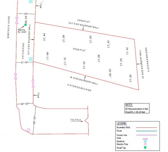
3. a) Study Area
This study focuses on the design of pedestrian bridge across the Auchi-Abuja Highway in front of Auchi Polytechnic, Auchi main entrance gate. b) Design consideration, calculations and analysis i.
4. Soil Test
The following geotechnical parameters were determined as follows:
(%) = ?????????????????????????????????????????????? % ??????????????????????????????????????? [2] Coefficient of uniformity (cu) = ??30 ??60 ? x D10 [3] Coefficient of uniformity (cu) = ??60 ??10 ? [4]ii. Specific Gravity Test (Gs) Given:
Gs = (M 2 -M 1 )/ (M 2 -M 1 )-(M 4 -M 3 )iii. Density Test Volume of cutter (V), mass of wet soil (M), Bulk density and dry density were computed as follows:
?? = ???? 2 ?? [5] M= M 2 -M 1 [6]Global The outputs of the design analysis indicate that the chosen sections for all the structural members of the footbridge are adequate in term of ultimate and serviceability considerations. The soil analysis shows that it would be able to withstand the load from the columns and vibrations from vehicular movement.
| S/N | Observation and Calculations | Determination | No |
| 1 | 2 | ||
| 1 | Density | 4267.0 | 4331.0 |
| 2 | Weighty of Empty Bottle (M 1 ) (g) | 26.6 | 26.6 |
| 3 | Weighty of Bottle +Sample (M 2 ) (g) | 56.6 | 56.6 |
| 4 | Weighty of Bottle + Sample H 2 O (M 3 ) (g) | 94.0 | 94.1 |
| 5 | Weighty of Bottle + Sample + H 2 O (M 4 ) (g) | 77.6 | 76.6 |
| 6 | M 2 -M 1 (g) | 30.0 | 30.0 |
| 7 | M 4 -M 3 (g) | 13.6 | 13.5 |
| 8 | Gs | 2.2 | 2.2 |
| Result | Density Gs = 5 | 2.2 | 2.2 |
| Field data, 2016 |
| S/N | Observation and Calculations | Determination | No |
| 1 | 2 | ||
| 1 | Core Cutter No | 501.0 | 502.0 |
| 2 | Internal Diameter (cm) | 10.0 | 10.0 |
| 3 | Internal Height (cm) | 13.0 | 13.0 |
| 4 | Mass Of Empty Core Cutter (M 1 )g | 900.0 | 900.0 |
| 5 | Mass Of Core Cutter With Soil (M 2 )g | 2900.0 | 2600.0 |
| 6 | Mass Of Wet Soil M= M 2 -M 1 | 2000.0 | 1700.0 |
| 7 | Volume Of Cutter (V) (cm 3 ) | 1021.0 | 1021.0 |
| 8 | Moisture Content | 0.1 | 0.2 |
| 9 | Bulk Density = Wt of Soil / Vol of Cutter (g/cm 3 ) | 1.96 | 1.67 |
| 10 | Dry Density (g/cm 3 ) | 1.75 | 1.45 |
| Field data, 2016 |
| Test No. | Load | Shear Stress at Failure (KN/M2) | Normal Stress (KN/M2) |
| 1 | 10 | 38.0 | 49.0 |
| 2 | 20 | 56.0 | 77.0 |
| 3 | 30 | 66.0 | 104.3 |
| Field data, 2016 |
| Time | Mass 1 | Maxx 2 | Mass 3 |
| (Seconds) | 10 kg | 20 kg | 30 kg |
| 5 | |||
| 10 | 1 | ||
| 15 | 1 | ||
| 20 | 1 | ||
| 30 | 1 | ||
| 60 | 1 | ||
| 90 | 1 | 13 | |
| 120 | 2 | 29 | 56 |
| 150 | 4 | 46 | 75 |
| 180 | 16 | 54 | 87 |
| 210 | 30 | 61 | 93 |
| 240 | 40 | 71 | 93 |
| 270 | 47 | 76 | 106 |
| 300 | 50 | 82 | 105 |
| 330 | 52 | 86 | 109 |
| 360 | 53 | 87 | 112 |
| 390 | 57 | 92 | 115 |
| 420 | 61 | 97 | |
| 450 | 62 | ||
| 480 | 65 | ||
| 510 | 65 | ||
| 540 | 66 | ||
| 570 | |||
| 600 | |||
| 630 | |||
| 660 | |||
| 690 | |||
| 720 | |||
| Field data, 2016 |
| ?H | ?e = 0.0565 ?H | ? = ? -?e | h = Ho -?H | Effective Stress | |||
| 0 | 0.00000 | 0.513 | 20.00 | 0.0000 | |||
| 0.86 | 0.04859 | 0.464 | 19.14 | 100.102 | |||
| 1.16 | 0.06554 | 0.448 | 18.84 | 200.204 | |||
| 1.43 | 0.08079 | 0.432 | 18.57 | 300.306 | |||
| 1.59 | 0.08984 | 0.423 | 18.41 | 400.408 | |||
| 1.69 | 0.09549 | 0.448 | 18.31 | 500.501 | |||
| Field data, 2016 | |||||||
| c) Design of Structural Elements | =4.62x10⁶/160 x 225 | ||||||
| i. Live Load for Footbridge | 4620000/36000=128.33mm 2 | ||||||
| For loaded length in excess of 30m | Width of the flanges is within the range of 0.5d | ||||||
| Live load, qk = k x 5.0KN/m 2 | [17] | =0.5x160mm=80mm | |||||
| 128.33/80=1.604; assume 2mm | |||||||
| Where, | Assume a plate size 80mmx2mm | ||||||
| K= nominal HA UDL for appropriate | Area=80x2=160mm 2 >128.33mm 2 | ||||||
| loaded length (in KN/m) 30 KN/m | [18] | The section chosen for the plate girder flanges as OK, the plate can be used. | |||||
| HA value for loaded length (32.4m) = 29.1 KN/m | Adopt the section 80mmx2mm | ||||||
| Therefore, | For the Web | ||||||
| K=29.1 KN/m | = 0.97 | ||||||
| 30 KN/m | T ? d/20 | [21] | |||||
| But qk = k x 5.0 KNlm 2 | T? 160/20=1.333 | ||||||
| Therefore, qk = 0.97 x 5.0 KNlm 2 = 4.85 KN/m 2 | Since T is a little bit small use the dimension of the | ||||||
| ii. Steel Plate for Treads | flanges for the web 80mmx2mm | ||||||
| Assume 300mm x 2400mm size | Section Classification | ||||||
| Plate Loading | Flanges | ||||||
| Dead load from plate | T=160mm; p y =225N/mm 2 | ||||||
| =25.55kg/m 2 x0.3mx2.4m+25.55kg/m 2 x0.147mx2.4m | But | ||||||
| =27.41kgx10=274.1Nx10 -3 =0.274KN Characteristic impose load | =2.4m | x0.3m | ?"=(275/py)½ | [22] | |||
| x4.85kN/m 2 =3.49KN Impose load on riser/tread=3.49x22=76.78KN | ?"=(275/225)½=1.11 b=80-2 =39 | ||||||
| Design load, n=1.4gk+1.6qk | 2 | ||||||
| =1.4x0.274+1.6x76.78=123.23KN | T=160mm | ||||||
| Bending moment | b/T=39/160=0.243 | ||||||
| BM max = WL/8 | [19] | For welded section b/T=13?" | |||||
| =123.23x0.3/8 =4.62KNM | b/T=13x1.11 = 14.43>0.24 | ||||||
| For short span girder | Therefore, the flanges are semi compact | ||||||
| Span/depth=12 | Serviceability Deflection under Imposed Load | ||||||
| Span/depth=15 2390mm/depth=15 | ? = 050 x 384 | EI wl 4 | [23] | ||||
| Depth=2390mm/15=159mm?160mm Since d=160mm>150mm; take p y =225N/mm 2 | W = 1.0gk + 1.0qk = 13.814+38.39=52.204KN | ||||||
| Area of flanges, Af=M/d x p y | [20] | Where, E=205x10 9 N/mm 2 | |||||