1. Introduction
ublic opposition is growing towards the use of fossil fuels as the conventional electricity generation ingredients because fossil fuels are responsible for emitting huge CO 2 and contributing global warming problems. Also because of the limited stock of fossil fuels, renewable energies can be the alternative. Among those renewable energies, wind energy is very fast growing, and it is expected that by 2020, almost 10% of global electricity generation will be provided by the wind energy [1].
Recently fixed speed wind turbine generation system lost its popularity mainly because it suffers various problems, particularly during the transient conditions. So, at present variable speed wind turbine generation system is more popular choice [2]. Due to variable speed operation, superior energy capture ability from wind, excellent power quality, higher efficiency, reduced losses, less mechanical stress on turbine, fractionally rated converter, separate control ability of active and reactive power make doubly fed induction generator (DFIG) one of the most popular choices in wind energy market [3,4].
Although DFIG has many unique advantages, it suffers from grid disturbances as its stator windings are directly connected to the grid, and rotor windings are connected to the grid via back to back power electronic converters. The shutdown of that DFIG based wind farm during a fault is the easiest solution but not the wise one as more and more wind power is integrated into the grid. Therefore various grid codes [5] have been defined to avoid the complete shutdown of a large wind farm. DFIG may experiences high current in both stator and rotor windings, DC-link overvoltage, torque oscillation, acute mechanical stress to the rotor shaft and gearbox during the fault condition. So, enhance the fault ride through (FRT), or low voltage ride through (LVRT) capability of DFIG is very important.
To enhance the FRT capability of the DFIG based wind generation system, many solutions have been proposed, which can be categorized into two groups.
? Using new converter modeling and control techniques. It increases the complexity of the system.
? Using auxiliary devices, also known as hardware solutions. It increases the overall cost of the system. fault current limiter (STFCL) [25], resistive type superconducting fault current limiter (SFCL) connected in a series with the DFIG rotor winding [26], superconducting magnetic energy storage (SMES) [27], nine-switch converter (NSC) instead of six-switch converter [28] are also proposed as a solution to improve the FRT capability of DFIG.
In previous work, it has proved that bridge type fault current limiter (BFCL) [3] is an excellent solution to enhance FRT capability of DFIG based variable speed wind generation system. As a new auxiliary device named parallel resonance fault current limiter (PRFCL) has a promising application in power systems [29]. Application of PRFCL to augment the FRT capability of DFIG based wind farm is reported in [30], and it has found from that paper that the PRFCL has better FRT augmentation capability than the BFCL. Now in this paper, the effect of increasing the switching frequency of power converters of DFIG during fault conditions is observed, and this switching frequency control (SFC) strategy is conjugated with the PRFCL (SFC-PRFCL) to augment the FRT capability of DFIG. Both symmetrical and asymmetrical faults are considered at the most vulnerable point of the system. In order to check the effectiveness of that SFC-PRFCL, its performance is compared with both the BFCL and the PRFCL. Simulation results show that SFC-PRFCL outperforms both the BFCL and the PRFCL. Simulations were carried out in PSCAD/EMTDC environment.
2. II.
3. Model System
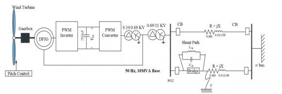
The effectiveness of the proposed SFC-PRFCL is demonstrated through a test wind energy conversion system. Here in Fig. 1, a DFIG (10 MVA) is connected to the point of common coupling (PCC). The output of the wind turbine is supplied to the utility grid through a 0.69/11-kV step-up transformer and double circuit transmission lines. The rotor of that DFIG is fed through a 0.34/0.69-kV step-down transformer and back-to-back converters named rotor side converter (RSC) and grid side converter (GSC) that use insulated gate bipolar transistors (IGBTs). A capacitor is connected to the DC side acts as the DC voltage source. The SFC-PRFCL is connected in series with one of the transmission lines to protect it. At the most vulnerable point of the system, both symmetrical and asymmetrical faults were considered.
4. III. Wind Turbine and DFIG Modeling
Modeling of the wind turbine, the DFIG, and the converter controllers are as follows.
5. a) Wind Turbine Modeling
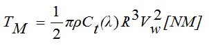
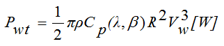
The turbine rotor, a shaft, and a gearbox unit are the primary components in the modeling of a wind turbine. Also, various physical and geometrical aspects have to take in consideration for proper modeling of a wind turbine. Normally a simplified method of modeling the wind turbine is used. The commonly used mathematical relations for the aerodynamic torque and mechanical power extracted from the wind can be given by [19]:
(1) (2)where is the air density, is the radius of the turbine, is the wind speed, and is the power coefficient given by (3) The relationship between t C and p C can be expressed as
(4)(5) (6)Here, wt ? is the rotational speed of the wind turbine, ? is the tip speed ratio, and ? is the blade pitch angle.
6. b) DFIG Modeling
Modeling of DFIG has described in many works. Here the Park's transformation model is chosen to model the DFIG. Two mass drive train model used in this study. Drive train model has a great impact on transient stability. The generator parameters and excitation parameters are given in Table I [19,31]. 2 shows the RSC controller which is actually a two level, six pulse, IGBT based power converter in this study. It regulates the terminal voltage to 1.0 pu. The active power and reactive power are controlled by d-axis current and q-axis current respectively. The Park's transformation is used to convert abc-to-dq0 and vice versa. Phase lock loop (PLL) provides the angle ?? ?????? and ?? ?? is the effective angle for that transformation. After getting ?? ???? and ?? ???? , those are through the dq0-to-abc transformation to produce three phase reference signal, then sent to pulse width modulation (PWM) signal generator block, so that it can generate pulses for the IGBT switches of the RSC.
Î?" ? ? ? Î?" = 17 . 0 ) 6 . 5 2 02 . 0 ( 2 1 ) , ( e p C ? ? ? ? ? ? ) ( ) ( p C t C = w wt V R ? ? = ) 1609 ( ) 3600 ( ? R = Î?" © 2018 Global Journals Global Journal of7. d) GSC Controller
Fig. 3 shows the GSC control block for this study which also contains two level, six pulse, IGBT based power converter. It controls the DC-link voltage to 1.0 pu. The DC-link voltage and the reactive power of GSC are controlled by d-axis current and q-axis current respectively. As an odd multiple of the third harmonics, a switching frequency of 1650 Hz is chosen in the normal condition which can minimize up to thirteenth harmonics [3].
In Fig. 2 and 3, quantities with '*' refer to reference value. Parameters of proportional integral (PI) are so chosen that they can give the optimum performance. Transfer functions are used in the controllers, and their parameters are also so chosen that they give faster response and take a shorter time to reach the normal operation. IV.
8. SFC-PRFCL
The modeling of the proposed SFC-PRFCL is described as follows.
9. a) PRFCL Configuration
Fig. 4 shows the per phase diagram of PRFCL [29]. It has two independent parts, namely the bridge part and the shunt part. This shunt part can be named as resonance part also.
Four diodes ?? 1 ? ?? 4 are there in the bridge part, which are arranged in a bridge configuration. Inside the bridge, a small valued DC reactor ?? ???? in series with an IGBT switch is placed as shown in Fig. 4. For safety purpose, a free-wheeling diode ?? 5 is equipped with the DC reactor ?? ???? . A very small value resistor ?? ???? is considered in series with ?? ???? to include the latent resistance of the DC reactor.
The shunt or resonance part is constructed of a capacitor ?? ??? and an inductor ?? ??? . To form an LC resonance circuit at line power frequency, they are arranged in parallel to each other as shown in Fig. 4.
D 5 R dc L dc IGBT D 1 D 2 D 4 D 3 L sh C sh10. b) PRFCL Operation and Control
In normal operating condition, the IGBT switch in Fig. 4 is in ON state. In the positive half cycle, the ?? 1 ? ?? ???? ? ?? ???? ? ?? 4 path and in the negative half cycle, the ?? 2 ? ?? ???? ? ?? ???? ? ?? 3 path carries the line current. So, the current through the DC reactor ?? ???? is in the same direction, and this is the DC current ?? ???? for ?? ???? . This ?? ???? offers no impedance for this DC current. There are some voltage drop in the bridge part during normal operating condition due to the latent resistance ?? ???? of the DC reactor, ON-state resistance of IGBT switch and diode forward voltage drop. But the aggregated voltage drop of those is ignorable compared to the large line voltage drop. So, this bridge part has no impact on normal operating condition. As the shunt path is in the parallel resonance condition, its impedance seems very high. Therefore in normal condition, the full line current is flown through the bridge part except some negligible leakage current. Now, when a fault occurs, the line current wants to rise very quickly, but the DC reactor ?? ???? does not permit this. So, safe operation for IGBT switch is ensured as ?? ???? limits the high ???? ???? ? value during fault. To take the turn OFF decision for IGBT switch during a fault and bypass the line current to the high impedance resonating shunt path, DC current ?? ???? through the DC reactor is compared with a threshold value ?? ??? . Here, ?? ??? is taken 1.3 times the nominal value of ?? ???? for optimum operation. When ?? ???? exceeds ?? ??? , IGBT switch gets a low gate signal ?? ð??"ð??"ð??"ð??" ???? and turned OFF. Per phase PRFCL controller is shown in Fig. 5. Some other parameters like the line current, the terminal voltage, the active power or the reactive power can be used for IGBT control, but the DC current ?? ???? through the DC reactor ?? ???? is used in this study. This is because ?? ???? is very sensitive to line current and has a faster rate of rise than line current and other parameters. After turning OFF of the IGBT, ?? ???? becomes zero. So, to resume the normal operation and turn ON the IGBT switch, another parameter has to choose. For that purpose, the voltage at PCC, ?? ?????? is chosen in this study. After the circuit breakers opening of the faulty section and isolating that faulty part, bus voltage starts to rise, and the system starts to recover. The ?? ?????? is compared with a reference value ?? ?????? which is set 90% of the nominal value of ?? ?????? . After starting the rise of bus voltage, when ?? ?????? exceeds ?? ?????? , the IGBT switch will get a high signal and normal operation resume as shown in Fig. 5.
11. c) PRFCL Design Consideration
To design the PRFCL, the ultimate task is to determine the values of shunt capacitor ?? ??? and shunt inductor ?? ??? . At power frequency, so many combinations of ?? ??? and ?? ??? would give the resonance condition. Standard values of ?? ??? are picked from [32], and ?? ??? is calculating considering the resonance at power frequency. At power frequency, many pairs of ?? ??? and ?? ??? are trialed, and among those, ?? ??? = 125 µ?? and ?? ??? = 80 ???? gave the best result during the fault. The values of ?? ???? and ?? ???? are picked 1 ???? and 0.3??? respectively, which give a time constant of 3.33 s. This is good enough for smoothing the DC reactor current.
12. d) SFC Configuration
To investigate the impact of increasing the switching frequency of the carrier wave during the fault condition, the proposed pulse generation system for both RSC and GSC is shown in Fig. 6. In both RSC and GSC, the triangular signal is used as the carrier wave of PWM operation. In Fig. 6, ?? ??_????????ð??"ð??"?? is the switching frequency in normal operating condition, and ?? ??_??ð??"ð??"ð??"ð??"???? is the increased switching frequency during the fault. How long the increased switching frequency ?? ??_??ð??"ð??"ð??"ð??"???? will remain active is decided by the IGBT gate signal ?? ð??"ð??"ð??"ð??"???? . As long as ?? ð??"ð??"ð??"ð??"???? in Fig. 5 remains a low state that means the IGBT switch in Fig. 4 is in OFF state, which indicates the fault situation, ?? ??_??ð??"ð??"ð??"ð??"???? is activated. Otherwise, in normal operating and after resuming the normal condition after the fault, ?? ??_????????ð??"ð??"?? is activated. A frequency of 1650 Hz is chosen as ?? ??_????????ð??"ð??"?? . And the increased switching frequency ?? ??_??ð??"ð??"ð??"ð??"???? is chosen eight times of ?? ??_????????ð??"ð??"?? in this study, which is implementable. This SFC strategy with PRFCL forms the SFC-PRFCL. V.
13. BFCL
To observe the effectiveness of the proposed SFC-PRFCL, its performance is compared with that the BFCL. Just like the PRFCL, the BFCL has two distinct parts namely the bridge part and the shunt path as shown in Fig. 7. Bridge part is exactly the same as PRFCL and the shunt path composed of a resistor ?? ??? in series with an inductor ?? ??? . The detail of BFCL topology is discussed in [3]. The same operation and control strategy is used for BFCL as PRFCL. The same controller is used for BFCL as shown in Fig. 5. The values of ?? ??? and ?? ??? are taken as the same procedure discussed in [3].
D 5 R dc L dc IGBT D 1 D 2 D 4 D 3 L sh R sh14. VI. Simulation Results And Discussion
Detail simulation results are described in the following subsections.
15. a) Simulation Considerations
Simulations were carried out by using PSCAD/EMTDC software. Here for transient analysis, a fixed wind speed of 15 m/s is considered. Duration of fault is too short to make any impact on wind speed, so fixed speed is considered. Analysis is carried out, and results are shown for most severe three line to ground (3LG) and most common line to ground (1LG) faults. Those faults were applied at the most vulnerable point of the system near the PCC denoted by point F in Fig. 1. Those faults were applied at 0.1 s and withdrawn at 0.6 s. Circuit breakers on the faulted line open and reclose at 0.2 s and 1.1 s respectively. Results are shown for a time duration of 0 s to 3 s, and per unit (pu) measurements are used. All those figures have a zoomed portion for better visualization. It is clear from the Fig. 9 that the SFC-PRFCL keeps the active power profile smooth during a 3LG fault. Output power goes very close to zero after the fault event with no controller case. Also, the breakers opening causes a large imbalance of output power. The BFCL and the PRFCL both have better active power profile than no case, but SFC-PRFCL gives the best response.
16. FRT Improvement by SFC-PRFCL for 3LG fault
The DFIG DC-link voltage profile is shown in Fig. 10 for 3LG fault. With no controller case, DC-link voltage profile is not good during the 3LG fault. It is seen that the DC-link voltage profile can be controlled within permissible limit by BFCL, PRFCL, and SFC-PRFCL. Among those, SFC-PRFCL gives the best DC-link voltage profile with least deviation of DC-link voltage from the nominal value.
17. Conclusion
The application of the SFC-PRFCL to enhance the FRT capability of DFIG is proposed in this paper. The effectiveness of the SFC-PRFCL is compared with that of the BFCL [3] and the PRFCL [30]. Following points are mentionable from the simulation results and discussions.
? The SFC-PRFCL is a very effective means to enhance the FRT capability of DFIG-based wind No Controller BFCL [3] PRFCL [30] SFC-PRFCL turbine generation system for both symmetrical and asymmetrical faults.
? The proposed SFC-PRFCL ensures more stable operation of the DFIG-based wind turbine generation system.
? Performances of BFCL and PRFCL are outperformed by the SFC-PRFCL in every aspect.
In our future work, the usefulness of SFC-PRFCL on a high capacity DFIG-based wind farm connected to a multi-machine power system will be considered.


| Characteristic | Value |
| Rated power | 10 [MVA] |
| Rated voltage | 0.69[kV] |
| Rated frequency | 50[Hz] |
| Stator resistance | 0.01[pu] |
| Wound rotor resistance | 0.01[pu] |
| Magnetizing inductance | 3.5[pu] |
| Stator leakage inductance | 0.15[pu] |
| Wound rotor leakage inductance | 0.15[pu] |
| Generator inertia constant | 0.3 [pu] |
| Turbine inertia constant | 3.0 [pu] |
| Shaft stiffness between two | 90 [pu] |
| masses | |
| DC-link voltage | 0.7 [kV] |
| DC-link capacitor | 25,000 [µF] |
| Device for the power converter | IGBT |
| c) RSC Controller | |
| Fig. |