1. INTRODUCTION
In this paper, we have proposed a new structure of a microstrip patch antenna which is designed for a single resonant frequency of 1.575 GHz. It is found that the resonance characteristics of the proposed antenna can be improved by using four rectangular slots of different sizes placed symmetrically into the patch. The return loss (?? 11 ) and bandwidth of the tetra-slotted rectangular MPA are increased remarkably in comparison with that of the conventional slot-less patch antenna. All the antennas are optimized and designed using CST Microwave Studio software for a various number of rectangular slots. The radiation pattern and In Section II the design procedure of optimization of tetra slotted MPA is described. The simulated and measured results of the proposed antenna are presented in Section III and IV, respectively. And finally, in Section V, we conclude by mentioning the research findings.
The schematic diagram of the proposed MPA and the dimensions of the incorporated slots have been II.
2. DESIGN OF THE PROPOSED MICROSTRIP PATCH ANTENNA
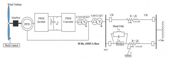
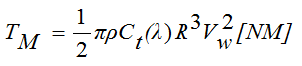
lobal Positioning System (GPS) is a well-known technology to determine the exact position and provide navigation functionality to connecteddevices. A GPS antenna uses signals from multiple satellites to identify the three-dimensional location. To achieve accurate positioning, the radiation characteristics of GPS antennas should be circularly polarized and have broad beam width. These attributes can be attained mainly by two types of antennas such as quadrifilar helix and microstrip patch antenna (MPA) [1]. However, small size, mechanical robustness, low fabrication cost and easy installation process have made microstrip patch antennas more favorable than quadrifilar helix antennas for GPS navigation. Moreover, microstrip patch antennas have applications in cellular communication, satellite communication, medical sector, etc. [2,3]. Despite the advantages, MPAs have some drawbacks such as low gain, narrow bandwidth, multiple resonances, less efficiency and low power handling capability [4][5][6][7]. Researchers have been working on MPAs to overcome all these flaws. For G instance, the return loss characteristics, bandwidth, and gain are improved by designing MPAs of rectangular [7], circular [8], and E-shaped patches [9]. Slot-loaded MPAs have also been made to enhance the performance furthermore [10]. Different feeding The patch width, ?? is expressed as
?? = ?? 0 2ð??"ð??" ?? ? 2 ?? ?? +1 (1)where ?? 0 is the free-space light velocity.
3. The expression for effective dielectric constant,
The extended length of the patch is determined from the following expression:
(5)
Î?"?? = 0.412 ? × (?? ?? ??ð??"ð??"ð??"ð??" + 0.3)( ?? ? + 0.264) (?? ?? ??ð??"ð??"ð??"ð??" ? 0.258)( ?? ? + 0.8)The expression for microstrip feed-line length (?? ð??"ð??" ) is The design of our proposed MPA starts by observing the characteristics of a conventional MPA (without slots). Keeping all the structural parameters same, a conventional MPA is first simulated. According to calculation, the antenna has a dimension of 91.2 mm (7) For ??/? > 1, which is satisfied for our chosen parameters given in Table-1, the length of the metallic patch, ?? is determined using the following equation:
?? ð??"ð??" = ?? 0 4ð??"ð??" ?? ? ?? ?? (6)The value of the width of the microstrip feed-line ?? ð??"ð??" is found from the results of best fit. By varying ?? ð??"ð??" from ??/10 to ??/5, the best fit has been found at 7.5 mm (see Table-1).
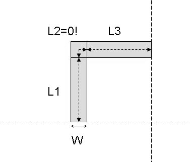
The gap between the patch and the feed line is often called the notch width. We have denoted this notch width by ?? ð??"ð??" and taken its value to be of 0.6 mm. For an inset feed MPA, it is also customary to define the distance by how much the microstrip feed-line will insert into the patch. We have denoted this distance by ?? ?? and the equation to determine this distance is mentioned below [15]: denoted by ?? and ??, respectively. The signal is applied to the patch through an inset feed transmission line having a length of ?? ð??"ð??" and a width of ?? ð??"ð??" . The feed line inset distance is represented by ?? ?? and is separated from the patch by a distance ?? ð??"ð??" . The substrate is symmetrically divided into four quadrants by vertical and horizontal dashed lines as shown in Fig. 1. The patch has been placed in the middle of the substrate.
where ?? ??ð??"ð??"ð??"ð??" is the effective length of the patch and Î?"?? is the extended length due to field fringing. The effective length ?? ??ð??"ð??"ð??"ð??" is determined from the following equation:
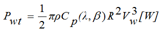
To design both slot-less (conventional) as well as slot-loaded (proposed) MPAs we have assumed FR-4 substrate whose dielectric constant (?? ?? ) and height (?) are 4.3 and 1.6 mm, respectively [13]. For GPS application, the resonant frequency (ð??"ð??" ?? ) of our proposed antenna is chosen at 1.575 GHz. With the aforementioned known parameters, the other unknown parameters such as patch length (??), patch width (??) and effective dielectric constant (? ?? ??ð??"ð??"ð??"ð??" ) are to be calculated by using the following equations [14]. by 117.0 mm. To improve the attributes of the conventional MPA, we have introduced few slots of different sizes placed symmetrically on the patch as shown in Fig. 1. After several attempts of optimization, we have found that the characteristics of the MPA are remarkably enhanced by two pairs of slots having different dimensions; one pair of slots is 18.66 mm×5.22 mm (?? 1 × ?? 1 ; large-slot), and the other pair is 4.79 mm×3.61 mm (?? 2 × ?? 2 ; small-slot).
?? ?????? = ?? 0 2?? ?? ? ?? ?? ?????? ?? ?? = 104. SIMULATION RESULTS
For the structural optimization and analysis of MPA, we have used CST Microwave Studio software. Simulation results of the resonant frequency, return loss, bandwidth, radiation pattern and directivity of MPA are presented in the following sections. The placement of the slots on the patch also plays a vital role in the overall performance of the antenna. The large-and small-slot pairs are described Figure 2 shows the return loss (?? 11 ) of conventional (without slot) as well as proposed (with slot) MPA. Even though the designed parameters are set to have a resonant frequency of 1.575 GHz, we have found the main return loss peak at (1.575+0.015) GHz for the conventional (Fig. 2(a)) and at (1.575-0.039) GHz for proposed antennas (Fig. 2(b,c)). Several other return loss peaks appear at resonant frequencies of 2.42 GHz, 2.90 GHz and 3.11 GHz for the conventional MPA. By introducing slots, these other return loss peaks are completely suppressed as shown in Fig. 2(b) and 2(c).
In Fig. 2(b) and 2(c), the results of return losses are shown for two-slot and four-slot MPA, respectively. For two slots into the patch, there is only one resonant frequency at 1.544 GHz which is 0.031 GHz less than the desired resonant frequency of 1.575 GHz (see Fig. 2(b)). For four-slot MPA, the return loss peak is obtained at a frequency of 1.536 GHz which is 0.039 GHz shorter than 1.575 GHz (see Fig. 2 (c)). by the distances (?? 1 , ?? 2 , ?? 3 ) and (?? 4 , ?? 5 , ?? 6 ), respectively from the edges of the patch (see Fig. 1.) For achieving a satisfactory result, the large-slot pair should be at a distance of ?? 1 = 12.94 mm, ?? 2 = 14.00 mm and ?? 3 = 12.23 mm. Similarly, the small-slot pair should be placed at a distance of ?? 4 = 23.83 mm, ?? 5 = 16.98 mm and ?? 6 = 6.15 mm. The optimized values of the structural parameters which give best simulation results are shown in Table-1. The results of simulation and measurements of different MPAs are discussed in the following sections.
From Fig. 2 it is seen that the magnitude of return loss has been increased significantly for our proposed patch antenna. The magnitude of ?? 11 is Found -21.94 dB for the conventional MPA (see Fig. 2(a)) whereas that of ?? 11 is obtained -40.22 dB and -50.72 dB for two-slot and four-slot MPA, respectively (see Fig. 2 (b, c)). Thus our proposed antenna has only one dominant resonant frequency with a very large ?? 11 magnitude. In Fig. 3, the obtained simulation results of the radiation patterns are shown. The main lobe magnitude (i.e., gain) of the conventional antenna is found to be 2.28 dB (see Fig. 3(a)). Introducing slots into the patch, the main lobe magnitude is obtained very close to the conventional one. For our proposed two-slot and fourslot MPAs, the main lobe magnitudes are found 1.97 dB and 2.12 dB, respectively. The main lobe direction has remained same at 0.0 deg for all MPAs.
From Fig. 3, it is seen that -3 dB beamwidths of conventional, two-slot, and four-slot MPAs are found at 92.0, 91.8, and 91.2 degrees, respectively. Thus -3 dB beamwidth for four-slot MPA is the smallest which means directivity has increased in comparison to the conventional one. Also, the side lobe levels of conventional, two-slot, and four-slot MPAs are obtained -12.5, -12.5, and -12.6 dB, respectively. Therefore, our proposed MPA has the lowest value of side lobe level and its efficiency has increased.
The VSWR value decreases towards unity at or near desired resonant frequency for our proposed structure. The simulated values of VSWR are 1.17, 1.02 and 1.005 for conventional, double-slotted (two-slot) and tetra-slotted (four-slot) MPA, respectively. Finally, the bandwidth and the directivity of our proposed tetraslotted antenna have been obtained 48.5 MHz and 7.13 dBi, respectively. The other directivities of the conventional and two-slotted MPA are quite similar to the proposed one.
5. MEASURED RESULTS
Among the simulation results of all three antennas, better characteristics are found for tetraslotted MPA which we have finally fabricated for experimental measurement. At first, the substrate has been cut into pieces having the dimensions of the antenna as given in Table-1. Then the patch antenna layout is printed on a tracing paper for photoresist masking. Lastly, chemical etching has been done to to be about -25 dB at 1.5 GHz. The deviation of return loss magnitude from simulated results may be due to the lossy FR-4 substrate and lack of precise fabrication of patch and slots with wet etching. At the resonant frequency, the bandwidth is found about 30 MHz. No significant return loss peaks at any other frequencies are found in the range of 1 GHz to 3 GHz. The measured radiation pattern is shown in Fig. 6. The main lobe radiation pattern is quite hemispherical, and the back lobe pattern is very small as obtained in simulation. Small back lobe characteristics represent that our proposed MPA has good directivity. All the measurements are taken in a room without the anechoic chamber. From Fig. 6 it is seen that the experimental results agree to a great extent with the simulated radiation patterns.


| ?4 {?? ??7 ?? ?? | 7 + ?? ??6 ?? ?? + ?? ??2 ?? ?? 2 ? ?? ??1 ?? ?? 6 ? ?? ??5 ?? ?? 1 + ?? ??0 } 5 + ?? ??4 ?? ?? ?? | 4 ? ?? ??3 ?? ?? | 3 |
| Parameters | Conventional MPA | MPA with two slots | MPA with four slots |
| Resonant Frequency, ð??"ð??" ?? (GHz) | 1.59, 2.42, 2.90, 3.11 | 1.54 | 1.54 |