1. Introduction
apid development in planer components is a result of growing interest in the field of wireless component design. An effective approach in designing passive microwave component is the substrate integrated waveguide (SIW) technology. In SIW dielectric material is sandwiched between two metal conducting plates and series of vias are inserted in the other two sides thus forming a rectangular waveguidelike structure modified in planer form [1]. SIW inherits almost all of the advantages of conventional rectangular waveguide like low insertion loss, high power handling capability in the microwave band and high-quality factor. Most of the properties of SIW like dispersion characteristics, propagation constant and field pattern are similar to that of waveguide counterparts. Several passive components like antennas, filters, power dividers and couplers are designed in the recent past using the manifold benefits of SIW. Several filters [2], couplers [3], oscillators [4], slot array antennas [5], sixport circuits [6], and circulators [7] are proposed since then .
In this paper, a conventional(linear) and a 90 o bent full mode SIW (FMSIW) bandpass filter embedded with new type of Electromagnetic Bandgap Structures are proposed, which exhibits the bandpass property of the microwave Ku-band.
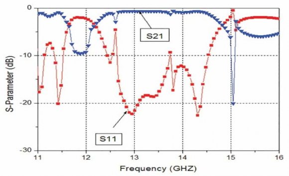
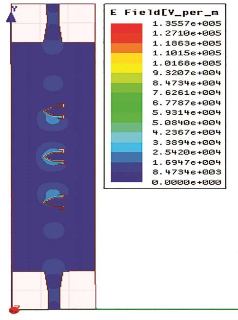
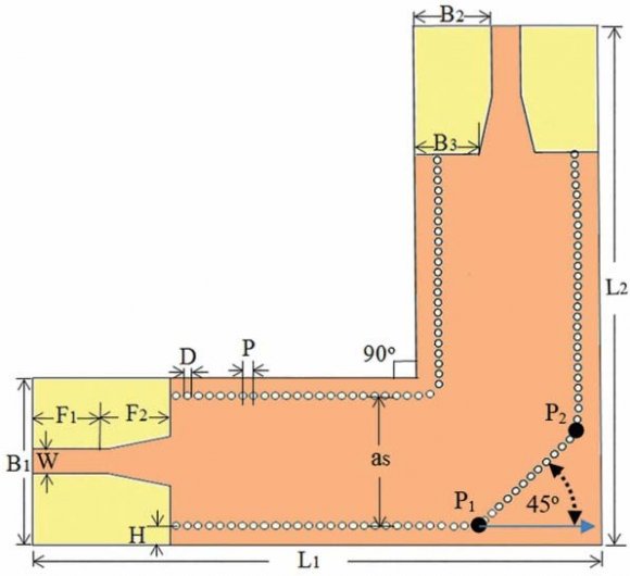
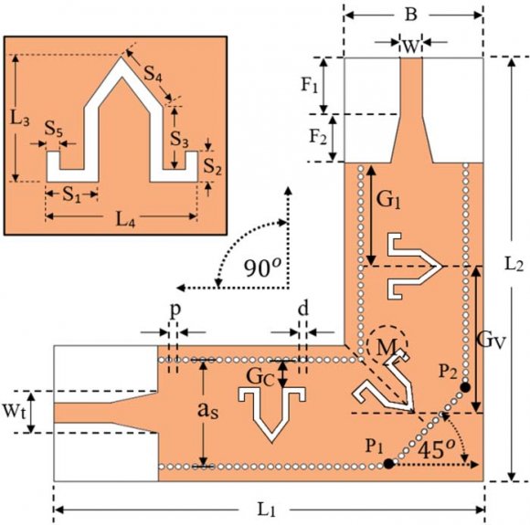
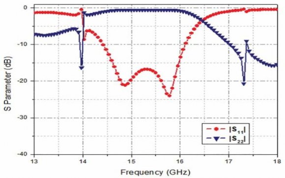
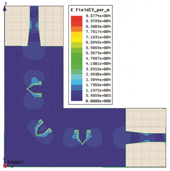
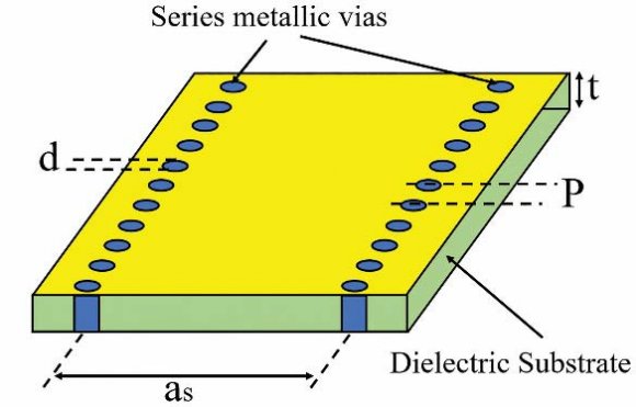
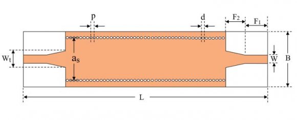
For designing high Q-factor and low loss filters, SIW which is realized by metallic vias on low loss substrates through printed circuit board is proved to be a useful technology [8]- [10]. In SIW fabrication process takes place with using two rows of conducting cylindrical vias embedded in a dielectric substrate that connects two parallel metal plates, and permit the implementation of a classical rectangular waveguide components in planar form, along with several printed passive circuitry, active devices and antennas as shown in Fig. 1. where, a s is the separation between via rows (center to center), a d is the width of the structure, d is the diameter, p is the pitch (as shown in Figure 1). The cut-off frequency of the SIW can be obtained by the following relation. Where c is the velocity of light in vacuum. Introduction of EBG in 180 o FMSIW results in production of transmission zero at around 15.04GHz, which complies the range of microwave Ku-band. The range of obtained passband is from 12.44 GHz to 14.53GHz with a minimum insertion loss of 0.71 dB. The E-field of the 180 FMSIW bandpass filter is shown in Fig 6 . Bending of 180 o FMSIW bandpass filter to 90 o FMSIW filter results in the production of transmission zero at around 17.31GHz with a transmission bandwidth lies in the range of microwave Ku-band. The range of obtained passband is from 14.61GHz to 15.97GHz with a minimum insertion loss of 0.58 dB. V.
2. II.
3. Design Equations
4. Parametric Analysis of EBG Structures
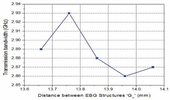
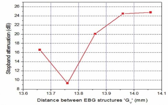
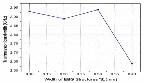
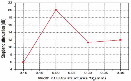
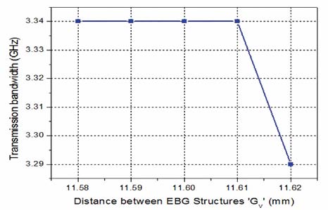
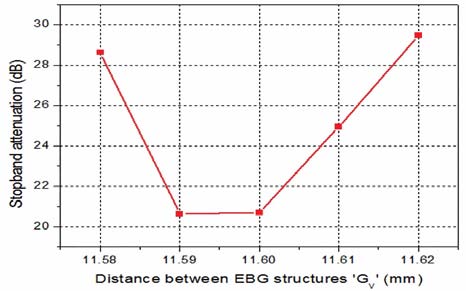
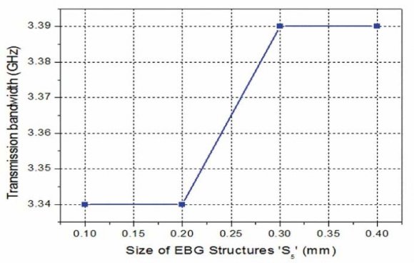
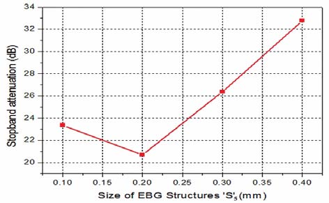
Microwave bandpass filter requires productive analysis of the technique to make the design effective. Several useful parameters of EBG elements are varied and the output is studied in details in this paper. Effective size of the EBG elements 'S 5 ' and the distance between successive EBG elements 'G v ' are studied. These parameters are found to have significant effect over the insertion loss, transmission band and isolation of the filter configurations. represents the variation which conveys that the stop band decreases from 16.59dB to 9.3dB as the distance increases from 13.66mm to 13.76mm but after 11.76mm the stop band attenuation increases with varying the distance by 0.1mm. The size of the EBG structures 'S 5 ' is also varied to achieve the size of EBG structure vs. transmission bandwidth and size of EBG structure vs. stop band attenuation graph to obtain greater control over passband and loss characteristics. Fig 12. shows the Size of EBG structure vs. Transmission bandwidth of EBG element. A clear observation is there that the transmission bandwidth slightly decreases when the size of the EBG element increases from 0.1mm to 0.2mm and again increases by small value when the size is increased to 0.3mm and gradually decreases as the size increases by 0.4mm. Table 2. and Table 4. represents simulated outcomes of the linear (180 o ) and 90 o bent FMSIW filters respectively. Based on the parametric analysis presented in this paper, successfully achieves good filter performance like minimum loss and high isolation property.
VI.
5. CONCLUSION
In this article, a brief discussion is there for obtaining the bandpass characteristics of 180 o FMSIW filter and 90 o FMSIW filter. 180 o FMSIW filter loaded with EBG structures bent down to 90 o and analyzed the bandpass characteristics for obtaining the desired passband. Bending of 180 o FMSIW filter to 90 o FMSIW filter and implementation of EBG structures on both designs are found to serve the purpose quite effectively. For better understanding, a detailed presentation for the analyses of several useful parameters of the EBG elements is there. Additionally, with bending the linear filter, length has been decreased. Thus, 90 o bent filters are more flexible than linear 180 o filters regarding the use and bandpass characteristics. Distance and size of
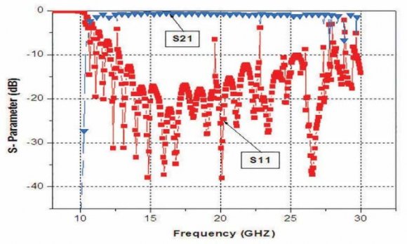
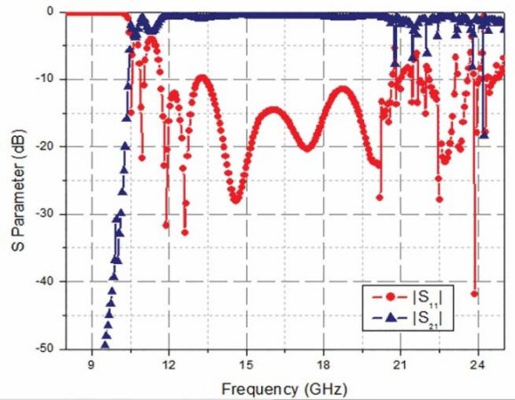
![Fig. 3: Scattering Parameters of basic 180 o FMSIW filter as designed on a substrate dielectric constant of 3.2 and 0.8mm thickness.b) 180 o FMSIW Filter Design With EBG StructuresThe basic 180 o FMSIW structure which is shown in Fig 2.acts as a high pass transmission line section. Tapered section between micro strip feed line and SIW section[14] avoids the impedance mismatch and designed as for 50? impedance matching. In this paper, implementation of introduced new type of EBG structures on the linear (180 o ) FMSIW filter creates additional resonance within the structure. Thus a considerable stop band attenuation arises in the range of Ku band with a transmission band of minimum insertion loss. The parametric analysis of EBG elements on the 180 o FMSIW structure shows that the magnitude and frequency of the stop band attenuation is highly dependent on the dimension of the EBG elements.Fig 4. and Fig 5. shows the EBG loaded 180 o FMSIW filter and its transmission characteristics respectively. Basic dimensional calculations can be obtained from [8].](https://engineeringresearch.org/index.php/GJRE/article/download/1716/version/100910/4-Planar-and-Angular-Modified-Substrate_html/19904/image-5.png)