1. I. Introduction
einforced soil and face walls have received a great deal of attention in recent years in urban construction and the related road and rail networks for trench stability as well as for access to dikes (Skinner and Row 2006). Geosynthetics are widely used as reinforcement components due to their many advantages, such as ease of use and economic benefits (Leshchinsky and Han 2004). Two of its common applications are soil reinforcement and securing the stability of dikes. Geosynthetics can prevent the extension of rupture levels by increasing the tensile resistance of the soil and by creating friction between the reinforcement and the soil to increase the stability and safety of dikes (Hatami and Bathurst 2006).
Many studies have been carried out to determine the geotechnics of reinforced sloped dikes in the last 25 years. Vidal (1969) proposed using dike reinforcement mechanisms to solve many geotechnical issues. On the other hand, using the finite element method in simulating dikes reinforced by polymer materials such as geosynthetics, under static and dynamic loads are capable of producing acceptable results as well. For example, using the finite element method, Ling et al. (2004) analyzed a face wall reinforced with geosynthetics and compared it to the experimental results, which suggested that the finite element method was highly accurate. Siavoshnia et al. (2010) evaluated the performance of a dike reinforced by geotextile fibers that was built on soft clay soil and modeled it using PLAXIS 2D. Their results show that a decrease in the dike's slope and its height from the bedding, as well as an increase in the hardness of the geotextile layers, led to a decrease in the dike's settlement. George and Hataf (2000) using PLAXIS, modelled the foundation of a soil barrier that was comprised of a column of sandy soil reinforced by geotextile layers. The results of their study showed that the geotextile layers led to an increase in the loadbearing capacity of the soil; however, using this system in very soft soils that contain organic materials resulted in decreased settlement of the foundation. Naini and Mirzakhanlari (2008) investigated the effect of strengthening granular soil with geotextiles and found that the load-bearing capacity of granular soils reinforced by geotextiles significantly increased the load-bearing capacity in the normal case. Ghaderi et al. (2005) examined the parameters that influence sloped fills reinforced by geotextile fibers. Their investigations showed that the stress distribution in the fill height was independent of the length of the geotextile layers. They also found that an increase in the length and number of geotextile layers led to an increase in the dike's safety factor against sliding. Noorzad and Mirmoradi (2010) investigated clay soils reinforced by geotextiles. Their experimental results showed that when the soil moisture increased, the soil's maximum tolerable stress decreased for both the "with" and "without" geotextile cases, but the axial strain increased and caused a rupture. Furthermore, an increase in the soil compaction resulted in increased resistance and soil axial strain in both cases.
2. R
© 2017 Global Journals Inc. (US)
3. II. Materials and Modeling Specifications
In the parametric study presented in this paper, the dike's slope height was 15 meter with the dike's ? Global Journal of Researches in Engineering ( ) Volume XVII Issue IV Version I
4. 37
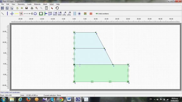
Year 2017 E materials in sand; and the soil layer beneath the dike (natural earth layer) was 8 m thick in soft clay. The length of the dike was 10 meter. In the first case and in order to consider the effect of the number of reinforcement layers, geotextile layers with equal lengths of 7 meter and variable vertical distances of 0.5, 0.6, 0.75 and 1 meter, were placed. The dike's slope angle was 1H:1.8V (61 degrees) in the first case. In the second case, in order to consider the effect of the dike's slope angle, geotextile layers of equal lengths of 7 m and equal vertical distances of 0.5 meter were placed. The dike's slope angle also was variable in this case, which was considered at 1H:1V (45 degrees), 1H:1.5V (56.3 degrees), 1H:1.8V (61 degrees) and 1H:3V (71.5 degrees). It is worthwhile to note that the dike being analyzed was subject to the effect of static loading (dike's weight). PLAXIS 8.5 software was used for modelling and the Mohr-Coulomb behavioral model was used for the intended materials.
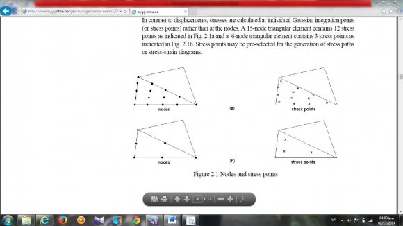
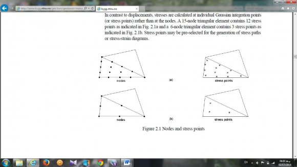
PLAXIS is an advanced finite element software that has many applications for analyzing deformations and sustainability in geotechnics projects. In twodimensional analyses, it is possible to choose two types of six-node and 15-node triangular elements. In the study presented in this paper, in order to achieve more accuracy in calculating stresses and strains, the 15node elements were chosen. In six-node elements, the element displacement approximation function is considered of the second order; and the hardness matrix of this type of element is obtained by using three stress points. On the other hand, in triangular 15-node elements, the displacement approximation function is considered of the fourth order; and its stress points for determining the hardness matrix are considered as 12 points. Fig. 1 shows the positions of the displacement points and stresses in these two types of elements (Brinkgreve and Vermeer 1998). Table 1 describes the specifications of the dike in this study, which was reinforced by geotextiles and the soil layer beneath (natural earth layer).
Table 1: Specifications of Reinforced Dike and its Soil Layer Beneath.
Since the reinforcing material of the dike was a geotextile, it was necessary to specify the geotextile in PLAXIS, which then considers the geotextile as a tensile element and is represented as an EA parameter (axial stiffness) in the software. Note that this value is different for different types of geotextiles; therefore, in order to consider their effect on the safety factor, maximum total displacement, maximum horizontal displacement, maximum vertical displacement and maximum shear strain created in the dike, the geotextile tensile stiffness was set at 1000 KN/m. The underground water level was
5. III. Calculations and Analysis of Results
As previously mentioned, the objective of the presented study was to investigate the effect of the following parameters of the dike on the safety factor: the number of reinforcement layers, the dike's slope angle, the maximum total displacement, maximum horizontal displacement, maximum vertical displacement and maximum shear strain created in the dike. Each parameter is discussed below.
6. a) Effect of the Number of Reinforcement Layers
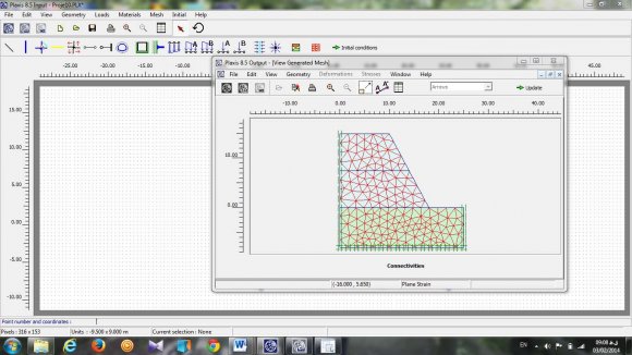
The numbers of reinforcement layers were set at 15 20, 25, and 30 in this experiment to determine this parameter's effect on the safety factor, the maximum total, horizontal, and vertical displacement and the maximum shear strain created in the dike when the tensile stiffness of the reinforcement layers was 1000 kN/m.
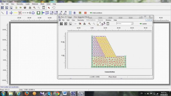
The type of netting on the reinforced dike when the number of reinforcement layers was15 as shown in Figure 3 and Figure 4 indicates the changes in the safety factor based on the number of reinforcement layers. It is obvious that when the number of reinforcement layers increased, the dike's safety factor increased. Also, it can be seen that when the number of reinforcement layers was 15, the safety factor was less than 1 and the dike was unstable. For the other quantities of reinforcement layers, the safety factor was always greater than 1 and the dike was stable. In fact, with an increase in the number of reinforcement layers, a probable sliding surface gradually moved away from the slope wall (i.e., as the number of reinforcement layers increased, the rigidity of the reinforced area increased). Also, Figure 5 shows that the extent of displacement decreased as the number of reinforcement layers increased. It can be seen that the maximum total displacement was more than the horizontal and vertical displacements and the maximum horizontal displacement was the least amount. In addition, when the number of reinforcement layers increased, the amount of tolerable stress in the dike increased and its deformation decreased. It is obvious from the figure that when the distance between the geotextiles decreased (an increase in layers), the maximum displacement decreased. Furthermore, when the number of layers was 15 (layers distance was1 m), the maximum displacement was large; but when the number of layers was 30 (layers distance was 50 cm), the maximum displacement decreased. This occurred because, in the case of relatively large distances between geotextiles, the stress between layers did not transmit well and the decrease in displacements (settlements) therefore was negligible compared to the case of small distances between layers. A 50 cm distance (the number of layers was 30), led to an ideal case of decreased displacement (settlement) in the dike because a lock was created between the soil particles as well as between the soil and the geotextile layers, which resulted in stress transmission from the upper to the lower layers, thereby greatly decreasing the dike's displacements. Figure 6 shows the maximum shear strain caused in the dike vs. the number of reinforcement layers. It can be seen that when the number of reinforcement layers increased, the amount of maximum shear strain in the dike decreased. Also, the maximum shear strain caused in the dike occurred when the number of reinforcement layers was 15, and the least shear strain caused in the dike was when the number of layers was 30.
7. Global Journal of Researches in Engineering
8. Global
9. b) Examining the Effect of the Dike's Slope Angle
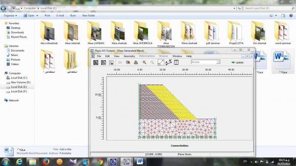
In this section, the effect of the dike's slope angle, which in this study were 45, 56.3, 61 and 71.5 degrees, on the safety factor, maximum final displacement, horizontal and vertical displacements, and maximum shear strain caused in the dike when the tensile hardness of the reinforcement layers was 1000 kN/m. Also, in Figure7, the type of netting for the reinforced dike when the slope angle was 45 degrees is shown. The changes in the safety factor vs. the dike's slope angle are shown in Figure 8. It can be seen that when the slope angle increased, the safety factor decreased. Also, when the dike's slope angle was 1H: 3V (71.5 degrees, the safety factor was less than the dike was unstable. In the other cases, the safety factor was greater than 1 and the dike was stable. In fact, it should be noted that the slope angle proved to be a very important parameter insofar as the extent of maximum tensile force caused in the reinforcement. layers; and the milder the slope was, the less the axial force created in the reinforcement. Figure 9 shows the maximum displacements created in the dike. It can be seen that when the dike's slope angle decreased, the maximum displacement created in the dike increased. Also, the least displacement of the dike was related to the maximum horizontal displacement; and when the dike's slope angle was 45 degrees, the least horizontal displacement was created. Moreover, since the maximum horizontal displacement commonly occurs at slope clevises, the milder the slope, the less the tuck of the soil was at clevises. A decrease in the dike's slope angle therefore had a greater effect on the maximum horizontal displacement of the dike. Figure10 shows the maximum shear strain caused in the dike vs. the dike's slope angle. It is easily seen that when the dike's slope angle decreased, the maximum shear strain created in the dike increased. Also, the least shear strain occurred when the dike's slope angle was 45 degrees, and the maximum shear strain occurred when the slope angle was 71.5 degrees.
10. Global
11. Fig. 10: Maximum Shear Strain Created in the Dike
12. IV. Conclusions
The conclusions of the study presented in this paper can be are summarized as follows:
1. Using geotextile layers can lead to improvement in a dike's performance; and more specifically, a dike reinforced by geotextiles has less slide and settlement than a dike without geotextile reinforcement. 2. With an increase in the number of reinforcement layers, the safety factor of a dike against slides increases insofar as the maximum total and the horizontal and vertical displacements, and the maximum shear strain created in the dike decreases. 3. With an increase in the number of reinforcement layers, a probable sliding surface gradually moves away from a slope wall and the rigidity of the reinforced area increases. 4. With an increase in a dike's slope angle, the dike's safety factor against a slide decreases; and the maximum total and the horizontal and vertical displacements as well as the maximum shear strain created in the dike increase. 5. The optimal case for the dike in this study occurred when the number of reinforcement layers was 30 and the dike's slope angle was 45 degrees.
©

| Parameter | Name | sand | clay | unit |
| Model of material behaviour | Model | Mohr-Coulomb Mohr-Coulomb | -- | |
| Type of material behaviour Soil unit weight above p.l. Soil unit weight below p.l. Horizental permeability Vertical permeability Young's modulus | Type ? wet ? sat K X K y E ref | Drained 17 21 0.5 0.5 30000 | Drained 15 18 10 -4 10 -4 3400 | --KN/m 3 KN/m 3 m/day m/day KN/m 2 |
| Poisson's ratio | ? | 0.3 | 0.33 | -- |
| Cohesion | C | 1 | 5.5 | KN/m 2 |
| Friction angle | ? | 34 | 24 | degree |
| Dilatancy angle | ? | 4 | 0 | degree |
| Interface reduction factor | R inter | 0.8 | -- | -- |
| Tensile stiffness of reinforcement | EA | 1000 | -- | KN/m |