1. I. Introduction a) Shear wall structure
he usefulness of shear walls in framing of buildings has long been recognized. Walls situated in advantageous positions in a building can form an efficient lateral-force-resisting system, simultaneously fulfilling other functional requirements. When a permanent and similar subdivision of floor areas in all stories is required as in the case of hotels or apartment buildings, numerous shear walls can be utilized not only for lateral force resistance but also to carry gravity loads. In such case, the floor by floor repetitive planning allows the walls to be vertically continuous which may serve simultaneously as excellent acoustic and fire insulators between the apartments. Shear walls may be planar but are often of L-, T-, I-, or E, C, Box shaped section to better suit the planning and to increase their flexural stiffness.
The positions of shear walls within a building are usually dictated by functional requirements. These may or may not suit structural planning. The purpose of a building and consequent allocation of floor space may dictate required arrangements of walls that can often be readily utilized for lateral force resistance. Building sites, architectural interests or client's desire may lead the positions of walls that are undesirable from a structural point of view. However, structural designers are often in the position to advice as to the most desirable locations for shear walls in order to optimize seismic resistance. The major structural considerations for individual shear walls will be aspects of symmetry in stiffness, torsional stability and available overturning capacity of the foundations (Paulay and Priestley, 1992). movable partitions, permanent equipment, a part of the live load, etc. While computing the seismic weight of columns and walls in any storey shall be equally distributed to the floors above and below the storey. Earthquake forces experienced by a building result from ground motions (accelerations) which are also fluctuating or dynamic in nature, in fact they reverse direction somewhat chaotically. The magnitude of an earthquake force depends on the magnitude of an earthquake, distance from the earthquake source(epicenter), local ground conditions that may amplify ground shaking (or dampen it), the weight(or mass) of the structure, and the type of structural system and its ability to with stand abusive cyclic loading. In theory and practice, the lateral force that a building experiences from an earthquake increases in direct proportion with the acceleration of ground motion at the building site and the mass of the building (i.e., a doubling in ground motion acceleration or building mass will double the load).This theory rests on the simplicity and validity of Newton's law of physics: F = m x a, where 'F' represents force, 'm' represents mass or weight, and 'a' represents acceleration. For example, as a car accelerates forward, a force is imparted to the driver through the seat to push him forward with the car(this force is equivalent to the weight of the driver multiplied by the acceleration or rate of change in speed of the car). As the brake is applied, the car is decelerated and a force is imparted to the driver by the seat-belt to push him back toward the seat. Similarly, as the ground accelerates back and forth during an earthquake it imparts back-and-forth(cyclic) forces to a building through its foundation which is forced to move with the ground. One can imagine a very light structure such as fabric tent that will be undamaged in almost any earthquake but it will not survive high wind. The reason is the low mass (weight) of the tent. Therefore, residential buildings generally perform reasonably well in earthquakes but are more vulnerable in high-wind load prone areas. Regardless, the proper amount of bracing is required in both cases.
2. c) Importance of Seismic Design Codes
Ground vibration during earthquake cause forces and deformations in structures. Structures need to be designed withstand such forces and deformations. Seismic codes help to improve the behavior of structures so that may withstand the earthquake effect without significant loss of life and property. Countries around the world have procedures outlined in seismic code to help design engineers in the planning, designing, detailing and constructing of structures.
i. An earthquake resistant has four virtues in it, namely
The regulations in these standards do not ensure that structures suffer no damage during earthquake of all magnitude. But, to the extent possible, they ensure that structures are able to respond to earthquake shaking of moderate intensities without a. Good Structural Configuration Its size, shape and structural system carrying loads are such that they ensure a direct and smooth flow of inertia forces to the ground.
3. b. Lateral Strength
The maximum lateral (horizontal) force that it can resist is such that the damage induced in it does not result in collapse.
c. Adequate Stiffness Its lateral load resisting system is such that the earthquake -indeed deformations in it do not damage its contents under low-to-moderate shaking.
d. Good Ductility Its capacity to undergo large deformations under severe earthquake shaking even after yielding is improved by favorable design and detailing strategies.
4. ii. Indian Seismic Codes
Seismic codes are unique to a particular region or country. They take into account the local seismology, accepted level of seismic risk, buildings typologies, and materials and methods used in construction.
The
5. d) Site Selection
The seismic motion that reaches a structure on the surface of the earth is influenced by local soil conditions. The subsurface soil layers underlying the building foundation may amplify the response of the building to earthquake motions originating in the bedrock.
For soft soils the earthquake vibrations can be significantly amplified and hence the shaking of structures sited on soft soils can be much greater than structural damage and of heavy intensities wit out total collapse. soil investigation should be carried out to establish the allowable bearing capacity and nature of soil. The choice of a site for a building from the failure prevention for structures sited on hard soils. Hence the appropriate Global Journal of Researches in Engineering ( ) Volume XVII Issue IV Version I
6. 12
Year 2017 E ground. The very loose sands or sensitive clays are liable to be destroyed by the earthquake, so much as to lose their original structure and thereby undergo compaction. This would result in large unequal settlements and damage the building. If the loose cohesion less soils are saturated with water they are likely to lose their shear resistance altogether during ground shaking. This leads to liquefaction. Although such soils can be compacted, for small buildings the operation may be too costly and the sites having these soils are better avoided.
For large building complexes, such as housing developments, new colonies, etc. this factor should be thoroughly investigated and the site has to be selected appropriately. Therefore a site with sufficient bearing capacity and free from the above defects should be chosen and its drainage condition improved so that no water accumulates and saturates the ground especially close to the footing level. e) Bearing capacity of foundation soil i. Hard-Those soils, which have an allowable bearing capacity of more than 10t/m2. ii. Medium-Those soils, which have an allowable bearing capacity less than or equal to 10t/m2. iii. Soft-Those soils, which are liable to large differential settlement or liquefaction during an earthquake. Soils must be avoided or compacted to improve them so as to qualify them either as firm or stiff. The allowable bearing pressure shall be determined in accordance with IS: 1888-1982 load test (Revision 1992). It is a common practice to increase the allowable bearing pressure by one-third, i.e. 33%, while performing seismic analysis of the materials like massive crystalline bedrock sedimentary rock, dense to very dense soil and heavily over consolidated cohesive soils, such as a stiff to hard clays. For the structure to react to the motion, it needs to overcome its own inertia, which results in an interaction between the structure and the soil. The extent to which the structural response may alter the characteristics of earthquake motions observed at the foundation level depends on the relative mass and stiffness properties of the soil and the structure.
Thus the physical property of the foundation medium is an important factor in the earthquake response of structures supported on it. There are two aspects of building foundation interaction during earthquakes, which are of primary importance to earthquake engineering. First, the response to earthquake motion of a structure founded on a deformable soil can be significantly different from that would occur if the structure is supported on a rigid foundation. Second, the motion recorded at the base of a structure or in the immediate vicinity can be different from that which would have been recorded had there been no building. Observations of the response of the buildings during earthquakes have shown that the response of typical structures can be markedly influenced by the soil properties if the soils are sufficiently soft. Furthermore, for relatively rigid structures such as nuclear reactor containment structures, interaction effects can be important, even for relatively firm soils because the important parameter apparently is not the stiffness of the soil, but the relative stiffness of the building and its foundation. In terms of the dynamic properties of the building foundation system, past studies have shown that the interaction will, in general, reduce the fundamental frequency of the system from that of the structure on a rigid base, dissipate part of the vibrational energy of the building by wave radiation into the foundation medium and modify the base motion of the structure in comparison to the free-field motion. Although all these effects may be present in some degree for every structure, the important point is to establish under what conditions the effects are of practical significance.
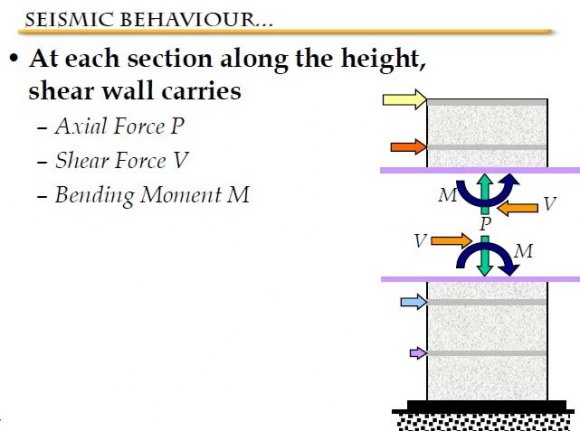
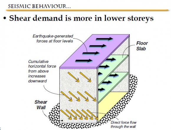
7. f) Seismic Behavior of RC Shear Wall
8. II. Methodology
Earthquake motion causes vibration of the structure leading to inertia forces. Thus a structure must be able to safely transmit the horizontal and the vertical inertia forces generated in the super structure through the foundation to the ground. Hence, for most of the ordinary structures, earthquake-resistant design requires ensuring that the structure has adequate lateral load carrying capacity. Seismic codes will guide a designer to safely design the structure for its intended purpose.
1. Equivalent Static Lateral Force Method (pseudo static method). 2. Dynamic Analysis.
i. Response spectrum method.
ii. Time history method.
9. a) Equivalent lateral Force (Seismic Coefficient) Method
This method of finding lateral forces is also known as the static method or the equivalent static method or the seismic coefficient method. The static method is the simplest one and it requires less computational effort and is based on formulae given in the code of practice.
In all the methods of analyzing a multi storey buildings recommended in the code, the structure is treated as discrete system having concentrated masses at floor levels which include the weight of columns and walls in any storey should be equally distributed to the floors above and below the storey. In addition, the appropriate amount of imposed load at this floor is also lumped with it. It is also assumed that the structure flexible and will deflect with respect to the position of foundation the lumped mass system reduces to the solution of a system of second order differential equations. These equations are formed by distribution, of mass and stiffness in a structure, together with its damping characteristics of the ground motion.
10. Dynamic Analysis
Dynamic analysis shall be performed to obtain the design seismic force, and its distribution in different levels along the height of the building, and in the various lateral load resisting element, for the following buildings:
The analysis of model for dynamic analysis of buildings with unusual configuration should be such that it adequately models the types of irregularities present in the building configuration. Buildings with plan irregularities, as defined in Table 4 of IS code: 1893-2002 cannot be modeled for dynamic analysis.
11. Dynamic analysis may be performed either by the TIME HISTORY METHOD or by the RESPONSE SPECTRUM METHOD Time History Method
The usage of this method shall be on an appropriate ground motion and shall be performed using accepted principles of dynamics. In this method, the mathematical model of the building is subjected to accelerations from earthquake records that represent the expected earthquake at the base of the structure.
12. Response Spectrum Method
The word spectrum in engineering conveys the idea that the response of buildings having a broad range of periods is summarized in a single graph. This method shall be performed using the design spectrum specified in code or by a site-specific design spectrum for a structure prepared at a project site. The values of damping for building may be taken as 2 and 5 percent of the critical, for the purposes of dynamic of steel and reinforce concrete buildings, respectively. For most buildings, inelastic response can be expected to occur during a major earthquake, implying that an inelastic analysis is more proper for design. However, in spite of the availability of nonlinear inelastic programs, they are not used in typical design practice because:
1. Their proper use requires knowledge of their inner workings and theories. design criteria, and 2. Result produced are difficult to interpret and apply to traditional design criteria , and 3. The necessary computations are expensive. Therefore, analysis in practice typically use linear elastic procedures based on the response spectrum method. The response spectrum analysis is the preferred method because it is easier to use.
13. III. Literature Review
Generally, the building configuration which is conceived by architects and then accepted by developer or owner may provide a narrow range of options for lateral-load resistant systems that can be utilized by structural engineers. By observing the following fundamental principles relevant to seismic responses, more suitable structural systems may be adopted (Paulay and Priestley, 1992):
1. To perform well in an earthquake, a building should possess simple and regular configurations. Buildings with articulated plans such as T and L shapes should be avoided. 2. Symmetry in plans should be provided, wherever possible. Lack of symmetry in plan may lead to significant torsional response, the reliable prediction of which is often difficult. 3. An integrated foundation system should tie together all vertical structural elements in both principal directions. Foundation resting on different soil condition should preferably be avoided. 4. Lateral force resisting systems with significantly different stiffness such as shear walls and frames within one building should be arranged in such a way that at every level of the building, symmetry in lateral stiffness is not grossly violated. Thus, undesirable torsional effects will be minimized.
Quite a few methods are available for the earthquake analysis of buildings; two of them are presented here: 2013) studied lateral displacement and inter-story drift on a square symmetric structure with walls at the centre and at the edges, and found that the presence of shear wall can affect the seismic behaviour of frame structure to large extent, and the shear wall increases the strength and stiffness of the structure.
c) b) Global Journal ofSagar K.et al., (2012) carried out linear dynamic analysis on two sixteen storey high buildings. It was concluded that shear walls are one of the most effective building elements in resisting lateral forces during earthquake. Providing shear walls in proper position minimizes effect and damages due to earthquake and winds.
Kumbhare P.S. et al., (2012) carried out a study on shear wall frame interaction systems and member forces. It was found that shear wall frame interaction systems are very effective in resisting lateral forces induced by earthquake. Placing shear wall away from center of gravity resulted in increase in the most of the members forces. It follows that shear walls should be coinciding with the centroid of the building.
Rahman A. et al., (2012) studied on drift analysis due to earthquake load on tall structures. In this study regular shaped structures have been considered. Estimation of drift was carried out for rigid frame structure, coupled shear wall structure and wall frame structure.
Anshuman et al., (2011) conducted a research on solution of shear wall location in multi storey building. An earthquake load was calculated and applied to a fifteen storied building located in zone IV. It was observed that the top deflection was reduced and reached within the permissible deflection after providing the shear wall. Kameshwari B. et al., (2011) analyzed the effect of various configurations of shear walls on high-rise structure. The drift and inter-storey drift of the structure in the following configurations of shear wall panels was studied and was compared with that of bare frame. Diagonal shear wall configuration was found to be effective for structures in the earthquake prone areas.
Based on the literature review, the salient objective of the present study have been identified as follows:
?14. a) Details of The Building
A symmetrical building of plan 38.5m X 35.5m located with location in zone V, India is considered. Four bays of length 7.5m& one bays of length 8.5m along X -direction and Four bays of length 7.5m& one bays of length 5.5m along Y -direction are provided. Shear Wall is provided at the center core of building model.
15. Structure 1:
In this model building with 30 storey is modeled as a (Dual frame system with shear wall (Plus Shape) at the center of building, The shear wall acts as vertical cantilever.
Structure 2: In this model building with 30 storey is modeled as (Dual frame system with shear wall (Box Shape) at the center of building ,The shear wall acts as vertical cantilever.
Structure 3: In this model building with 30 storey is modeled as (Dual frame system with shear wall (C-Shape) at the center of building, The shear wall acts as vertical cantilever.
Structure 4: In this model building with 30 storey is modeled as (Dual frame system with shear wall (E-Shape) at the center of building ,The shear wall acts as vertical cantilever. When a structure is subjected to earthquake, it responds by vibrating. An example force can be resolved into three mutually perpendicular directionstwo horizontal directions (X and Y directions) and the vertical direction (Z). This motion causes the structure to vibrate or shake in all three directions; the predominant direction of shaking is horizontal. All the structures are primarily designed for gravity loads-force equal to mass time's gravity in the vertical direction. Because of the inherent factor used in the design specifications, most structures tend to be adequately protected against vertical shaking. Vertical acceleration should also be considered in structures with large spans those in which stability for design, or for overall stability analysis of structures. The basic intent of design theory for earthquake resistant structures is that buildings should be able to resist minor earthquakes without damage, resist moderate earthquakes without structural damage but with some non-structural damage. To avoid collapse during a major earthquake, Members must be ductile enough to absorb and dissipate energy by post elastic deformation. Redundancy in the structural system permits redistribution of internal forces in the event of the failure of key elements. When the primary element or system yields or fails, the lateral force can be redistributed to a secondary system to prevent progressive failure.
The result obtained from the analysis models will be discussed and compared as follows:
It is observed that ? The time period is 6.298 Sec for structure1 and it is same for different type of soil. ? The Frequency is 0.159 cyc/sec for structure1 and it is same for different type of soil. ? The time period is 5.785 Sec for structure2 and it is same for different type of soil. ? The Frequency is 0.173 cyc/sec for structure2 and it is same for different type of soil. ? The time period is 6.415 Sec for structure3 and it is same for different type of soil. ? The Frequency is 0.156 cyc/sec for structure3 and it is same for different type of soil. ? The time period is 6.375Sec for structure4 and it is same for different type of soil. ? The Frequency is 0.157 cyc/sec for structure4 and it is same for different type of soil. ? The time period is 6.382 Sec for structure5 and it is same for different type of soil. ? The Frequency is 0.157 cyc/sec for structure5 and it is same for different type of soil. ? Pier Shear Forces V3 in X direction for soft soil >Medium soil > hard soil.
? Pier Shear Forces V3 in X direction for soft soil >Medium soil > hard soil. ? Pier Torsion in X direction for soft soil >Medium soil > hard soil. ? Pier Torsion in Y direction for soft soil <Medium soil < hard soil.
16. VII. Conclusions
In this paper, reinforced concrete shear wall buildings were analyzed with the procedures laid out in IS codes. Seismic performance of building model is evaluated.
From the above results and discussions, following conclusions can be drawn: ? Building with box shape Shear Walls provided at the center core showed better performance in terms of Pier Forces. ? The shear wall and it is position has a significant influenced on the time period. The time period is not influenced by the type of soil. ? There is considerable difference in Pier Moment with a Different type of soils and structures. ? There is considerable difference in Pier shear force with a Different type of soils and structures. ? There is not considerable difference in Pier axial forces with a Different type of soils and structures. ? It is evident that Pier Torsion in X direction for all structures in soft soil more than Medium soil and more than hard soil. ? It is evident that Pier Torsion in Y direction for soft soil less than Medium soil and less than hard soil. ? shear is effected marginally by placing of the shear wall, grouping of shear wall and type of soil. The shear is increased by adding shear wall due to increase the seismic weight of the building. ? The moment resisting frame with shear walls are very good in lateral force such as earthquake and wind force. The shear walls provide lateral load distribution by transferring the wind and earthquake loads to the foundation. And also impact on the lateral stiffness of the system and also carries gravity loads. ? It is evident that shear walls which are provided from the foundation to the rooftop, are one of the excellent mean for providing earthquake resistant to multistory reinforced building with different type of soil. ? The vertical reinforcement that is uniformly distributed in the shear wall shall not be less than the horizontal reinforcement .This provision is particularly for squat walls (i.e. Height-to-width ratio is about 1.0).However ,for walls whit height-to-width ratio less than 1.0, a major part of the shear force is resisted by the vertical reinforcement. Hence, adequate vertical reinforcement should be provided for such walls. ? Based on the analysis and discussion ,shear wall are very much suitable for resisting earthquake induced lateral forces in multistoried structural systems when compared to multistoried structural systems whit out shear walls. They can be made to behave in a ductile manner by adopting proper detailing techniques. ? According to IS-1893:2002 the number of modes to be used in the analysis should be such that the total sum of modal masses of all modes considered is at least 90 percent of the total seismic mass. Here the maximum mass for structure 2 is 94.7 percent and minimum mass for structure 1 is 86.71 percent.
17. Global


| 5. | |
| d) | |
| Year 2017 | |
| 15 | |
| Regular buildings: Those greater than 40m in height in zones IV and V, those greater than 90m in height in zone II and III. Irregular buildings: All framed buildings higher than 12m | ( ) Volume XVII Issue IV Version I E Researches in Engineering |
| in zones IV and V, and those greater than 40m in height | |
| in zones II and III. |
| Year 2017 | |||||||
| 21 | |||||||
| Table: Pier Forces Story Pier | Load Case/Combo | Location | Structure -1 Structure -2 Structure -3 Structure -4 Structure -5 P P P P P kN kN kN kN kN | Global Journal of Researches in Engineering ( ) Volume XVII Issue IV Version I E | |||
| 1ST | P3 | 12DLRLLEQXP | Top | -31716.3887 -33051.4245 -34550.8106 | -6497.8574 | -33427.2625 | |
| 1ST | P3 | 12DLRLLEQXP | Bottom | -31976.2637 -33311.2995 -34810.6856 | -6627.7949 | -33687.1375 | |
| 1ST | P3 | 12DLRLLEQYP | Top | -31716.3887 -25170.9557 -32781.7792 -13631.3189 -33874.5211 | |||
| 1ST | P3 | 12DLRLLEQYP | Bottom | -31976.2637 -25430.8307 -33041.6542 -13761.2564 -34134.3961 | |||
| Table: Pier Forces | Structure -1 Structure -2 Structure -3 Structure -4 Structure -5 | |||||||
| Story Pier | Load Case/Combo | Location | P | P | P | P | P | |
| kN | kN | kN | kN | kN | ||||
| 1ST | P3 | 12DLRLLEQXP | Top | -31716.3887 -35888.3932 -35187.6619 -3330.9739 | -33266.2891 | |||
| 1ST | P3 | 12DLRLLEQXP | Bottom | -31976.2637 -36148.2682 -35447.5369 -3460.9114 | -33526.1641 | |||
| 1ST | P3 | 12DLRLLEQYP | Top | -31716.3887 -25170.9557 -32781.7792 -13631.3189 -33874.5608 | ||||
| 1ST | P3 | 12DLRLLEQYP | Bottom | -31976.2637 -25430.8307 -33041.6542 -13761.2564 -34134.4358 | ||||
| Year 2017 | ||||
| 22 | ||||
| Global Journal of Researches in Engineering ( ) Volume XVII Issue IV Version I E | Table: Pier Forces Story Pier 1ST P3 1ST P3 1ST P3 1ST P3 | Load Case/Combo 12DLRLLEQXP 12DLRLLEQXP 12DLRLLEQYP 12DLRLLEQYP | Location Top Bottom Top Bottom | Structure -1 Structure -2 Structure -3 Structure -4 Structure -5 P P P P P kN kN kN kN kN -31716.3887 -38331.3385 -35736.0616 -983.1011 -33127.6731 -31976.2637 -38591.2135 -35995.9366 -1113.0386 -33387.5481 -31716.3887 -25170.9557 -32781.7792 -13631.3189 -33874.595 -31976.2637 -25430.8307 -33041.6542 -13761.2564 -34134.47 |
| 5 Structure -5 | M3 | kN -m | -61.6944 | -17.1098 | 11107.3586 | 34855.9706 | |
| Structure - | M2 | kN -m | -65.0181 | -290.8369 | -57.7674 | 63.9359 | |
| -4 Structure -4 | M3 | kN -m | 1861.0597 | 6530.9935 | -716.6361 | 1031.4388 | |
| Structure -1 Structure -1 Structure -2 Structure -2 Structure -3 Structure -3 Structure | Location M2 M3 M2 M3 M2 M3 M2 | kN-m kN-m kN-m kN -m kN -m kN -m kN -m | Top 429.3134 -285.376 54.4708 1200.3755 1.9394 237.7991 -17.4689 | Bottom -796.6308 -244.1397 -444.1125 -365.0748 -496.6401 403.2212 21.225 | Top -10.3264 29494.5797 0.9942 19086.5309 0.9679 18817.9303 21.4569 | Bott om 4.0607 41193.3422 -3.6328 27973.8752 -4.8413 31627.6809 138.7803 | |
| Load | Case/Combo | 12DLRLLEQXP | 12DLRLLEQXP | 12DLRLLEQYP | 12DLRLLEQYP | ||
| Table: Pier Forces | Story Pier | 1ST P3 | 1ST P3 | 1ST P3 | 1ST P3 | ||
| medium soil |
| M for structures with the load combination 1.2 (DL+LL+EQXP) &1.2 (DL+LL+EQYP) in hard soil | Table: : Pier Structure Forces -1 Structure -1 Structure -2 Structure -2 Structure -3 Structure -3 Structure -4 Structure -4 Structure -5 Structure -5 | Story Pier Load Case/Combo Location M2 M3 M2 M3 M2 M3 M2 M3 M2 M3 | kN-m kN-m kN-m kN-m kN-m kN-m kN-m kN-m kN-m kN-m | 1ST P3 12DLRLLEQXP Top 723.8721 -285.376 90.3001 2004.6271 2.5903 397.1246 -30.9703 3853.6925 -69.8743 -79.7196 | 1ST P3 12DLRLLEQXP Bottom -1333.0941 -244.1397 -739.2339 -609.6748 -826.1452 673.3795 37.6294 10781.7386 -528.5339 -15.7496 | -57.7657 18572.599 1ST P3 12DLRLLEQYP Top -10.3264 49447.15 0.9942 31874.5067 0.9679 31425.9437 38.0596 -716.6361 | 63.9367 58222.2947 1ST P3 12DLRLLEQYP Bottom 4.0607 68956.455 -3.6328 46716.3716 -4.8413 52818.2271 246.0468 1031.4388 | 23 Year 2017 Global Journal of Researches in Engineering ( ) Volume XVII Issue IV Version I E |
| Force, V for structures with the load combination 1.2 (DL+LL+EQXP) &1.2 (DL+LL+EQYP) in | hard soil | V2 V3 V2 V3 V2 V3 V2 V3 V2 V3 | kN kN kN kN kN kN kN kN kN kN | 11. 7818 -587. 7046 -746. 9434 -237. 0097 78. 93 -236. 7816 1979. 4418 19. 5999 18. 2771 -131. 0456 | 11. 7818 -587. 7046 -746. 9434 -237. 0097 78. 93 -236. 7816 1979. 4418 19. 5999 18. 2771 -131.0456 | 5574. 0871 4. 1106 4240. 5328 -1. 322 6112. 081 -1. 6598 499.45 59. 4249 11328. 4845 34. 7721 | 5574. 0871 4. 1106 4240. 5328 -1. 322 6112. 081 -1. 6598 499.45 59. 4249 11328.4845 34. 7721 |
| Stor y Pier L oad Case/Combo Location | 1ST P3 12D LR LLEQXP T op | 1ST P3 12D LR LLEQXP B ottom | 1ST P3 12D LR LLEQYP T op | 1ST P3 12D LR LLEQYP B ottom |
| soft soil |
| medium soil |
| Table: Pier Forces | Structure -1 Structure -2 | Structure -3 | Structure -4 Structure -5 | |||||
| Story | Pier | Load Case/Combo | Location | T | T | T | T | T |
| kN-m | kN-m | kN-m | kN-m | kN-m | ||||
| 1ST | P3 | 12DLRLLEQXP | Top | -57.8883 | -31.8229 | -32.2595 | -17.3115 | -33.9525 |
| 1ST | P3 | 12DLRLLEQXP | Bottom | -57.8883 | -31.8229 | -32.2595 | -17.3115 | -33.9525 |
| 1ST | P3 | 12DLRLLEQYP | Top | 46.5531 | 41.9152 | 92.9513 | 35.9013 | 85.1595 |
| 1ST | P3 | 12DLRLLEQYP | Bottom | 46.5531 | 41.9152 | 92.9513 | 35.9013 | 85.1595 |
| Table: Pier Forces | Structure -1 Structure -2 Structure -3 Structure -4 Structure -5 | |||||||
| Story | Pier | Load Case/Combo | Location | T | T | T | T | T |
| kN-m | kN-m | kN-m | kN-m | kN-m | ||||
| 1ST | P3 | 12DLRLLEQXP | Top | -75.9256 | -43.2792 | -43.873 | -24.9942 | -46.1738 |
| 1ST | P3 | 12DLRLLEQXP Bottom | -75.9256 | -43.2792 | -43.873 | -24.9942 | -46.1738 | |
| 1ST | P3 | 12DLRLLEQYP | Top | 66.1147 | 57.0047 | 126.4138 | 51.8336 | 115.8184 |
| 1ST | P3 | 12DLRLLEQYP | Bottom | 66.1147 | 57.0047 | 126.4138 | 51.8336 | 115.8184 |
| 2 (DL+LL+EQXP) &1.2 (DL+LL+EQYP) |
| in hard soil |
| Static Dynamic | % % | 91.54 99.97 | 99.97 |
| Dynamic | % | 94.54 | 91.83 |
| Static | % | 99.99 | 99.97 |
| Dynamic | % | 94.59 | 91.85 |
| Static | % | 99.98 | 99.97 |
| Static Dynamic | % % | 99.99 94.7 | 99.98 91.46 |
| Static Dynamic | % % | 99.82 86.71 | 99.79 87.46 |
| Item Type Item | Acceleration UX | Acceleration UY | |
| Case | Modal | Modal |
| -5 | |
| Structure | |
| -5 | |
| Structure | |
| 4 | |
| Year 2017 26 Journal of Researches in Engineering ( ) Volume XVII Issue IV Version I E | Structure -1 Structure -2 Structure -Structure -4 Structure -3 Structure -1 Structure -2 Structure -3 |
| Table: Pier Forces |
| It is observed that | ||
| Shear Wall forces (Pier Forces) for structure 1 | ||
| ? Pier Torsion in X direction for soft soil >Medium soil | ? For the Pier axial forces in X direction There is not | |
| > hard soil. | considerable difference for soft Soil, Medium soil & | |
| ? Pier Torsion in Y direction for soft soil <Medium soil | Hard soil. | |
| < hard soil. | ? Pier Moment M2 in X direction for soft soil <medium | |
| It is observed that | soil < hard soil. | |
| Shear Wall forces (Pier Forces) for structure 4 | ? Pier Moment M3 in X direction for soft soil =medium | |
| Year 2017 28 Global Journal of Researches in Engineering E ( ) Volume XVII Issue IV Version I | ? Pier axial forces in X direction for soft Soil <Medium soil < Hard soil ? Pier Moment M2 in X direction for soft soil >medium soil > hard soil. ? Pier Moment M3 in X direction for soft soil <medium soil < hard soil. ? Pier Moment M2 in Y direction for soft soil <Medium soil < hard soil. ? Pier Moment M3 in Y direction for soft soil >Medium soil > hard soil. ? Pier Shear Forces V2 in X direction for soft soil <Medium soil < hard soil. ? Pier Shear Forces V3 in X direction for soft soil >Medium soil > hard soil. ? | soil = hard soil. ? Pier Moment M2 in Y direction for soft soil =Medium soil = hard soil. ? Pier Moment M3 in Y direction for soft soil <Medium soil < hard soil. ? Pier Shear Forces V2 in X direction for soft soil =Medium soil = hard soil. ? Pier Shear Forces V3 in X direction for soft soil >Medium soil > hard soil. ? Pier Torsion in X direction for soft soil >Medium soil > hard soil. ? Pier Torsion in Y direction for soft soil <Medium soil < hard soil It is observed that Shear Wall forces (Pier Forces) for structure 2 ? Pier axial forces in X direction for soft Soil >Medium soil > Hard soil ? Pier Moment M2 in X direction for soft soil <medium soil < hard soil . ? Pier Moment M3 in X direction for soft soil <medium soil < hard soil . ? Pier Moment M2 in Y direction for soft soil =Medium soil = hard soil . ? Pier Moment M3 in Y direction for soft soil <Medium soil < hard soil . ? Pier Shear Forces V2 in X direction for soft soil >Medium soil > hard soil. ? Pier Shear Forces V3 in X direction for soft soil >Medium soil > hard soil. ? Pier Torsion in X direction for soft soil >Medium soil > hard soil. ? Pier Torsion in Y direction for soft soil <Medium soil < hard soil. It is observed that Shear Wall forces (Pier Forces) for structure 3 ? Pier axial forces in X direction for soft Soil >Medium soil > Hard soil |
| ? Pier Moment M2 in X direction for soft soil <medium | ||
| soil < hard soil. | ||
| ? Pier Moment M3 in X direction for soft soil <medium | ||
| soil < hard soil. | ||
| ? Pier Moment M2 in Y direction for soft soil =Medium | ||
| soil = hard soil. | ||
| ? Pier Moment M3 in Y direction for soft soil <Medium | ||
| soil < hard soil. | ||
| ? Pier Shear Forces V2 in X direction for soft soil | ||
| <Medium soil < hard soil. |
| Year 2017 |
| 29 |
| E |