1. I. Introduction
he Heat transfer under convective boundary condition is common in heat exchangers [1]. The metal-foam-filled channels are proposed to increase the heat transfer area between hot and cold flows in plate heat exchangers [2]. The metallic foam is more and more used in thermal applications due to its convenient hydrodynamic and mechanic properties: porosity (in general ? 90%), high permeability and strength.
Pei-Xue et al. [3]report that the local heat transfer increase with increasing in flow rate and it decrease along the channel. Their numerical results show that there is a difference between the fluid particle temperature and the solid one which demonstrate the importance of non-equilibrium model. Z.G. Qu., et al. [4] found that the flow resistance maybe decreases with high porosities, density of pores and the metallic foam thickness report. The optimal porosity correspond the T maximum Nusselt number; the latter increases with decreasing in fluid-solid conductivity report. The results of Degan. G et al. [5] show that the permeability K has a significant influence on the convective heat transfer, where the heat transfer is best with high permeability values. Jeng, Tzer-Ming [6] present an experimental study of heat cooling of metallic foam blocs, they found that the Nusselt number may be intensified with factor varying between 3 and 5 compared to the smooth channel. Brahim MADANI et al. [7] indicate that the three-dimensional cellular structure of the foam acts as a mixing promoter. They report that the dispersion of the results obtained on similar metallic foams shows that the control and the understanding of the phenomena of flow in such media must pass through a thorough and precise analysis of their structures. The results of Hamadouche et al. [8] demonstrate that the insertion of metallic foam in turbulent flow participates in the enhancement of heat transfer with factor of 300% compared to the smooth channel. Kouidri at al. [9] characterized three metallic foam, with different surface roughness, their results show that the pressure drop increase from the smooth to the rough one, they report also that the permeability changes from type of flow to another.
The present work consists to studying the thermal and hydrodynamic performances of an HVAC Heating coil situated in air treatment station. The latter is considered as a porous medium (metal foam) generating of heat. The physical problem is simplified to a flow between two adiabatic plates, through a porous medium, generating of heat. The tested metallic foams are made from Copper and Aluminum.
2. II. Problem Description
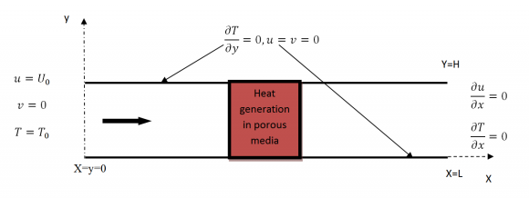
We consider an air flow between two horizontal plates. The channel is divided into three parts: inlet, outlet and the porous medium generating of heat (Fig 1). The first zone (inlet) has an establishment length L1 equal to 5H. The second zone, which has a length L2-L1, is considered as HVAC heating coil with a porous medium. The third zone (outlet) has an establishment length of 5H. We noted that the height H is equal to 1cm and the thickness of metallic foam is equal to cm. The upper and lower walls are assumed to be adiabatic. Keywords: HVAC, metallic foam, forced convection, heat transfer.
3. III. Mathematical Formulations and Modeling
The used method to derive the discretization equations is the finite volume with the SIMPLE algorithm. The structural mesh is adopted with 25000 nodes after studying the sensibility of mesh.
The conservation equations for a twodimensional stationary laminar flow, considering the thermal equilibrium, taken from the reference [10] are presented in the equations: 1, 2, 3 and 4. The used metallic foam was characterized by Kouidri et al. [9]. The Aluminum foam has the same geometric characteristics to the copper one. Figure 1: Physical problem and computational domain. The permeability is used as a characteristic length in Reynolds equation (Eq. 5):
4. Mass conservation equation
5. Momentum conservation equation
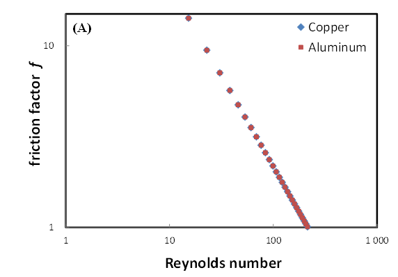
The same for the friction factor f which is calculate on basis of permeability (Eq.6)
The efficiency of the HVAC heating coil is given by the Eq. 7:
Where Qgen represents the heat flux generated in the porous medium (Heating coil), it equals to 5000000 W/m3. And Qabs represents the heat flux absorbed by the fluid between the inlet and outlet of the porous medium. It is calculate on basis of Eq. 8:
6. IV. Results
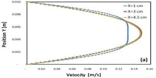
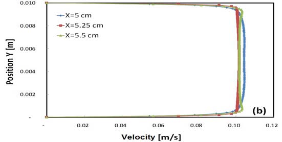
7. a) Velocity profile
Figure 3 (a) shows the velocity profile at the inlet of the channel, which is established before reaching the entrance of the porous medium, where the maximum velocity is at the center of the Y axis. We noted that the length of the channel at the inlet is 5 times greater than its height, which is sufficient for the establishment of a laminar regime. An explicative scheme of the boundary conditions is represented in Fig. 2.
8. ???= ?? ??????
?? ð??"ð??"??ð??"ð??" (7) (5) ( 6) Figure 4 shows the pressure drop, along the porous medium, for Aluminum and copper metallic foam. It is obvious that the two metallic foam samples present the same pressure drop because they have the same geometric characteristics. The pressure drop vary linearly with the velocity. Using a linear regression, the correlation between the pressure drop and the velocity may be writing following Eq. 9:
Q abs = ?? * ?? ?? * (?? ?? ??? ?? ) (8)The form of this equation is similar to the one given by Darcy [11] (Eq. 10), which demonstrate that the flow regime is Darcian.
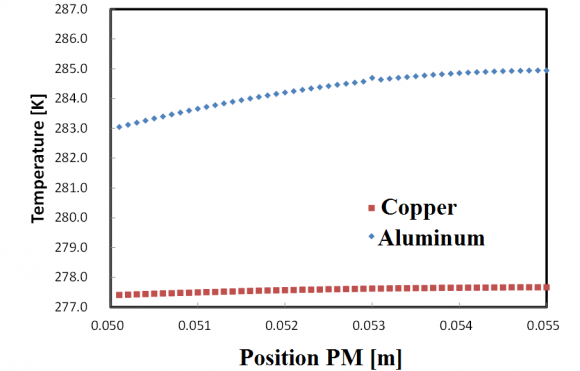
In the present simulations, the constant (µ/K) is equal to 2773.5 as is shown in Fig. 4 Figure 6 shows a comparison between the present simulations and the data given by the literature [9,12], for different material of metallic foam, the results are closed to those given by Kouidri et al. [9], this is due to the fact that the same geometric characteristics were introduced in the present simulations. Figure 7 presents the temperature distribution along the porous media, averaged on the Y axis, It is obvious that the evolution is logarithmic along the porous medium, for the two metallic foam samples.
In the same flow conditions, velocity and heat flux, the Aluminum sample gives the highest temperature; it can be interpreted by its calorific capacity which is more important compared to the copper one. This characteristic of Aluminum metallic foam is very important in HVAC heating coil, because it permits to have an important blowing temperature with minimum of dissipate energy. Copper [9] NiFeCrAl [9] Aluminum [11] Simulation Copper
9. Simulation Aluminum e) HVAC heating coil efficiency
The HVAC heating coil is calculated on basis of Eq. 7, presented in previous paragraph.
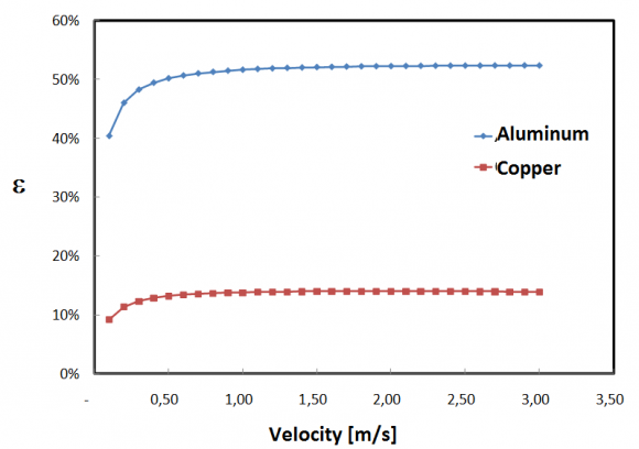
Figure 8 depicts the HVAC heating coil (made from porous media) efficiency, we remark that the efficiency in the case of Aluminum foam increase from 40% to 50% depending on the inlet velocity. The latter is constant for the velocity > 1.5 m/s.
On other hand, the Aluminum foam gives an efficiency 5 times more important compared to the copper one, this is due certainly to its important calorific capacity.


| D p (mm) | D lig (mm) | Ligament type | Porosity (%) | PPI | Permeability | |
| Copper | 1.2 | 0.187 | Triangular | 93 | 18 | 6.40E-09 |