1. I. Introduction
he performance of a golf club is evaluated from various viewpoints, such as the flying distance of a golfball after impact, the size of sweet area, and the sidespin, etc. Especially, the distance is always attached importance by most players. The design of the golf club, which matches to the users with different skill, becomes increasingly important, and many researches have been reported in this area. Iwatsubo et al. [1] investigated optimum rigidity of the head to maximize the release velocity of the ball. In their study, the impact phenomenon is simulated as a model of spring-massdamper system with a few degrees of freedom. They proposed the concept of impedance matching. In their later work [2], they tried to apply the concept of impedance matching to a three-dimensional model, and discussed the boundary condition for calculating the natural frequencies of clubhead and ball. Winfield and Tan [3] studied the optimization of clubhead loft and swing elevation angles for maximum distance. They also studied the optimum geometric shape of the clubface to minimize dispersion in off-center hits [4]. In their studies, the rigid models were used in the numerical analyses. deflection [5] and the mass distribution in the clubhead [6]. However, research on the detailed design of the clubhead, for instance, the thickness distribution of the head is scarce. To this problem, the authors proposed an approach to optimize the thickness distribution of a clubface so that the initial velocity of a golf ball gets to the maximum [7]. The authors also discussed the optimization of a golf club to reduce the side spin of a golf ball [8]. Our work was followed by Petersen and McPhee [9] who optimized the thickness distribution of a clubface to maximize the initial velocity of a golf ball with a procedure of three-stages design. Recently, some studies have been reported on the acoustics design of a golf club [10], [11]. In addition, Naruo and Mizota studied the aerodynamics of a golf ball experimentally [12], [13], and their work makes it be possible to numerically simulate the flying trajectory of the ball while designing a golf club by numerical approach.
In this study, firstly, the shape optimization of a clubhead for maximizing the distance of a flying ball with a constraint on volume of the clubhead is treated. The thickness distribution of the clubface, the shape of clubhead and the mass distribution are set to be the design variables. To overcome the difficulty that the sensitivity cannot be derived analytically in this problem, we choose the basis vector method for shape optimization. As same as our previous work, we also create the basis vectors by using the eigenmodes that can be obtained from modal analysis. Secondly, the optimization of a golfball for maximizing the flying distance and improving the feeling at impact is treated. The Design of Experiment is used to optimize thickness and material properties of each layer of a multi-piece ball. Finally, numerical examples are provided to show the effectiveness of presented approach to the optimal design of golf clubhead and ball.
2. II. Formulation of Optimization of Clubhead
In general, for a shape optimization problem, it is necessary to derive the design sensitivity that expresses the relation between the variation of an objective function and the variation of the design variables. However, it is difficult to be derived analytically in impact problem due to the use of explicit method for impact simulation. In this case, numerical techniques, such as the finite difference approach, the response surface method and the basis vector method can be used. In this study, since the number of design variables, which are the thickness distribution of the golf club, is large, the use of finite difference approach and the response surface method are very costly. Another reason why we do not use the finite difference approach is that it has worse accuracy than the use of basis vector method because of the rounding error. Therefore, we chose the basis vector method to use for shape optimization.
3. a) Basis Vector Method
In the basis vector method for shape optimization, the change of the grid's locations C ? , that is, the shape variation is calculated as a linear combination of perturbation vectors, each weighted with its respective design variable
) 2 1 ( N , , , i i ? = ?. The perturbation vector is the difference between a basis vector
) 2 1 ( N , , , i i ? = Cand the original locations of grids 0 C . That is
) ( 0 0 2 2 0 1 1 C C C C C C C ? + + ? + ? = N N ( ) ( ) ? ? ? ? ? (1)Where N is the number of basis vectors, which is usually smaller than degrees of freedom of design in order to reduce the computation time. Using basis vector method, the original shape optimization problem is exchanged to the problem of finding the optimal solution of weight coefficient ) , , , (
N i i ? 2 1 = ? .In general, this approximate method cannot guarantee the objective to reach the optimum solution. The accuracy of the solution depends on the selection of the basis vectors.
4. b) Optimization Formulation
Consider a shape optimization for maximizing an objective function f, the flying distance of a ball, with a constraint on the volume m of the head, by using basis vector method. Since the impact problem is a nonlinear problem, we cannot obtain the optimal solution by one cycle of optimization analysis. Assuming that the shape variation is small enough in one cycle of optimization, we can get the approximate linear relations between i ? and the variation of f, m as following:
? = = N i i i f f 1 ? ? ? (2) ? = = N i i i m m 1 ? ? ?(3)subjected to 0 = m ? This is a linear programming problem, which can be solved by LP algorithm. In this study, we exchange this problem to a stationary problem of a Lagrange functional expressed as
? ? ? ? ? ? ? ? ? + + = ? ? ? = = = N i i N i i i N i i i A m f L 1 0 2 2 1 1 1 ? ? ? ? ? ? ? (5)Where 0 0 > ? is used to control the length of one step, and to guarantee a unique solution. 1 ? , 2 ? are Lagrange multipliers. Taking the variation of L, we can obtain the necessary conditions as
? ? ? ? ? ? ? ? ? ? ? = ? = ? ? ? = ? = ? ? ? = ? + ? ? + ? = ? ? ? ? = = 0 0 0 2 1 0 2 2 1 1 2 1 N i i N i i i i i i i A L m L m f L ? ? ? ? (6) Then ) 2 1 ( N , , , i i ? = ? , 15. ? and 2
? can be obtained from these conditions. Using the weight coefficient i ? , the shape is modified as Eq.1 for one cycle. The cycle is iterated until the objective function is convergent. Year 2017 A III. Numerical Model and Generation of Basis Vectors
6. a) Numerical Model for Impact Simulation
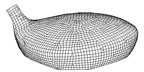
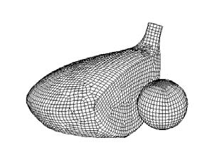
The analysis model of a hollow clubhead and a ball is shown in Fig. 1. The clubhead is discretized with shell elements, and the ball is discretized with solid elements.
7. b) Generation of Basis Vectors for Thickness of Clubface
The generation of basis vectors is a complex and time consuming process. It requires experience and design sense. In this study, for convenience, the basis vectors for thickness variations of clubface are created from eigenmodes. The eigenmodes can be obtained from modal analysis. The procedure to create basis vectors is 1) Undertake a modal analysis of design domain and select some of the eigenmodes.
2) Calculate the difference in the eigenmodes and the original locations of grids as the perturbation vector of displacement. 3) Exchange the perturbation vectors of displacement for those of thickness, and then obtain the basis vectors of thickness variation. 10 eigenmodes are selected to generate the basis vectors, and some of them are shown in Fig. 2.
8. c) Generation of Basis Vectors for Shape of Clubhead
4 shape basis vectors are generated. As shown in Fig. 3, 3 of them are obtained from the deformation of clubhead under different static loads and boundary conditions. Another one represents the variation of the loft angle, and it is obtained by changing the loft angle from 10 degree to 10.5 degree.
9. d) Setting of Balance Weights
In order to optimize the mass distribution, 2 balance weights are set to the clubhead. The positions are shown in Fig. 4 with red dots. The perturbation of each vector is set to 2g. The balance weights are treated as the same as other basis vectors.
10. IV. Optimization Analysis of Golf Clubhead
As shown in Fig. 1, the optimization analysis of a hollow clubhead is treated to maximize the flying distance of a golfball.
11. a) Analysis Conditions and Material Properties
The clubhead impacts the ball at the center point with an initial velocity of 42m/s. The swing elevation angle is set to 3 degree. Total time of the analysis is 500?sec with each analysis time step of 0.1?sec. The clubface is made of TiSP700 of which material properties are Young's modulus=110GPa, Poisson's ratio=0.33, density=4540kg/m3. The crown and sole are made of Ti64 of which material properties are Young's modulus=110GPa, Poisson's ratio=0.3, density=4420kg/m3.
A 3-piece golfball consisted of a cover layer, a silicon rubber layer and a core is used in impact simulation. The materials of the ball are assumed as viscoelastic, and their parameters were identified by impact tests. Figure 5 shows the viscoelastic model for materials of the cover layer, the silicon rubber layer, and the core. The mechanical properties of each material are shown in Table 1. Since we have confirmed through prior analyses that the flying distance of the ball is chiefly influenced by the thickness of the clubface, the design domain of thickness distribution is restricted to the clubface. In addition, the trajectory and the flying distance of the golfball is calculated according to references [12], [13].
12. Table 1: Material Properties of golf ball b) Analysis Result of Clubhead Optimization
After optimization analysis, the flying distance of the ball increased by about 3.6%, from 205.1m to 212.5m. Figure 6 shows the optimized thickness distribution of the clubface (a) and the shape (b) after 10 iterations. The thickness of the clubface was denoted by color. It is confirmed that the thickness gradually decreased from the bottom to the top of the clubface. In contrast to this, only a small change in the shape is confirmed, except the loft angle which was changed from 10.0 degree to 12.3 degree. It is also found that the balance weights were changed from 2g both to 6.5g and 6.8g, respectively. From the optimized result, it is considered that, in the case of a center shot, there is no strong relation between the flying distance and the shape of the clubhead comparing with the thickness distribution, the loft angle and the mass distribution.
13. Core
14. V. Optimization of Golfball
A long distance golfball is demanded by most players, and a soft feel is also preferable because it is easy to control. The optimal design of a 3-piece golfball for maximizing the flying distance with a soft feel at impact is discussed here. Since the sensitivity function is also difficult to be derived, a numerical method, Design of Experiments is used for the optimization.
15. a) Formulation of Optimization of Golfball
Figure 7 shows a typical 3-piece golfball consisted of a cover layer, a silicon rubber layer and a core. It is known that the polymeric material properties of which the golfball is composed can be changed easily during the manufacturing process. Here we treat the densities and young's moduli of the 3 pieces as the design variables. These values are assumed to be able to change from 95% to 110% of original values shown in Table 1. The thickness of the cover and the silicon rubber are assumed to be able to change from 1.5mm to 3mm and from 0mm to 3mm, respectively.
Consider an optimal design of the ball to maximize the flying distance impacted by a wood club and have a soft touch impacted by a 5-iron club. The soft touch is expressed as a contact time between ball and club. Then the optimization problem can be stated as (8) (9) Where L is the flying distance of golfball impacted by a wood club, T is the contact time between a 5-iron club and ball, M is the weight and D is the diameter of ball, W 1 , W 2 are the weight coefficients, respectively, d cov is the thickness of cover layer, d sil is the thickness of silicon rubber layer, is the density of cover, is the density of silicon rubber, is the density of core and E 1cor is the viscoelastic constant of core.
16. b) Analysis Result of Golfball Optimization
An approach of Design of Experiment is used for the optimization process. As shown in Table 2, the problem is set to a 6 factors 4 levels experiment. Orthogonal array L64 is used and the experiment is conducted numerically by computer simulation as a substitute for actual experiment. Both the weight coefficients W 1 , W 2 are set to 0.5. Table 3 shows the optimum solutions and the value of objective function after 64 times simulation. It is found that the objective function increased about 4.9% from an initial value.
17. VI. Conclusion
Numerical optimizations of a clubhead and a golfball were studied. In the optimization of a clubhead, the thickness distribution, the shape, and the balance weights were optimized to maximize the flying distance of a golfball. The basis vector method was applied to the optimization process, and the basis vectors were created by using eigenmodes. In the optimization of a golfball, approach of Design of Experiment was used to optimize the thickness and material properties of each layer of a multi-piece golfball for maximizing the flying distance and improving the feeling at impact. The effectiveness of our approaches was demonstrated by numerical examples.