1. I. Introduction
ao Huy Bich and Vu Do Long [1] used the analytical method to analyze the dynamics response of imperfect functionally graded material shallow shells subjected to dynamic loads. Nivin Philip, C. Prabha [2] analyzed static buckling of the stiffened composite cylindrical shell subjected to external pressure by the finite element method. Nguyen Thai Chung and Le Xuan Thuy [3] used the finite element method to analyze the dynamic of eccentrically rib-stiffened shallow cylindrical shells on flexible couplings under blast loadings. Lin Jing, Zhihua Wang, Longmao Zhao [4], Gabriele Imbalzano, Phuong Tran, Tuan D. Ngo, Peter V.S. Lee [5], Phuong Tran, Tuan D. Ngo, Abdallah Ghazlan [6] analyzed dynamic response of the composite shells and cylindrical sandwich shells under blast loading. Yonghui Wang, Ximei Zhai, Siew Chin Lee, Wei Wang [7] succeeded in analyzing the dynamic responses of curved steel-concrete-steel sandwich shells subjected to blast loading by the numerical method. Anqi Chen, Luke A. Louca and Ahmed Y. Elghazouli [8] analyzed dynamic behaviour of cylindrical steel drums under blast loading conditions. However, studies on the calculation of shell structure under the effect of the shock waves are few, especially of the shells with a hole.
In order to develop the study approach to the shallow cylindrical shells, in this paper, the authors set the algorithm and computer program to analyze the dynamics of rib-stiffened shallow cylindrical shells with abatement holes under the effect of the shock wave loads. Couplings on the shell borders are elastic supports with the tension-compression stiffness k.
2. II. Computational Model and Assumptions
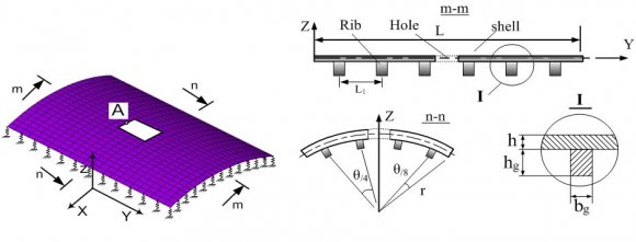
Considering the eccentrically rib-stiffened shallow cylindrical shell on elastic supports, being described by springs with stiffness k. The shell is subjected to a layer shock wave. Because the shell is shallow, the shock-wave presssure affecting can be considered to be uniformly distributed over the surface of the shell (Figure 1).
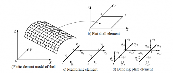
The assumptions: Materials of the shell are homogeneous and isotropic; the rib and shell are linearly elastically deformed and have absolutely adhesive connection; loading process works, no cracks appearing around the hole. q 3 q 1 q 4 q 5 q 6 q 7 q 8 q 9 q 10 q 11 The stiffened ribs are divided into 2-node spatial beam elements, each node has 6 degrees of freedom (Figure 3). The linearly elastic supports are described by bar elements, that are under tension and compression along its axis denoted by x, each node of the element has one degree of freedom (Figure 4) [9], [10].
3. D
4. b) Flat shell element describes the shell
Each node of the shell element is composed of 6 degrees of freedom: u i , v i , w i , ? xi , ? yi , ? zi . Displacement of any point of the element can be written as [9]: x, y ,t , x, y ,t , x, y ,t ? = ? ? = ? ? = ? where u, v, and w are the displacements along x, y and z axes, respectively; superscript " o " denotes mid plane displacement; and ? x , ? y , and ? z are rotations about the x -axis, y -axis and z -axis, respectively. Strain vector components are:
( ) ( ) ( )x y xy u v u v , , , x y y x ? ? ? ? ? = ? = ? = + ? ? ? ?(2)Relationship stress -strain can be written as
{?} = [D]{?},(3)where [D] is a matrix of relationship stress -strain.
Using Hamilton's principle for the elements [12]:
( ) q , q ? are vector of nodal displacements, and vector of nodal velocities, respectively. Considering the case not mention the damping, from (4) leads to the following:
{ } { } { } e e e e H H d 0 dt q q ? ? ? ? ? ? ? + = ? ? ? ? ? ? ? ? ? ,(5)The kinetic energy T e of the elements is determined by the expression [9]:
{ } [ ] [ ] { } { } [ ] { } e T T e e e e VT s e e e 1 T q N N dV q 2
1 = q M q , 2 ? ? ? ? = ? ? ? ? ? ? ? ? ? ?(6)where [N] is function matrix of flat shell elements [9], [10], V e is element volume, [ ] s e M is element mass matrix, ? is specific volume of materials. The total potential energy U e is determined by:
{ } [ ] { } T s e e e e 1 U q K q 2 = ,(7)In which [ ] s e K is stiffness matrix of flat shell elements.
Total external work due to mechanical loading is determined by:
{ } { } { } { } { } { }f dV 2 1 q f d A q f , 2 = + + + ? ?(8)with A e is element area, { } f -concentrated force vector of the elements [9], [10].
Substitute ( 6), ( 7), ( 8) into ( 4), ( 5), we have the differential equation describing the vibration of the shell element in matrix form as follow:
[ ] { } [ ] { } { } e e es s e e M q q F , K
+ = ?? (9)where {q e } is the vector of nodal displacements, {F e } is the mechanical force vector.
[T] e is the coordinate axes transition matrix [9].
5. b) Space Beam Element Describes the Rib
Displacement in any node of the bar with (x, y) coordinates is identified as follows [9]:
( ) ( ) ( ) ( ) 0 y z u u x, y, z, t u x, t z x, t y x, t = = + ? ? ? ( ) ( ) ( ) 0 x v v x, y, z, t v x, y, t z x, t , = = ? ? (11) ( ) ( ) ( ) 0 z w x, y, z, t w x, t y x, t = + ?where, the subscript "0" represents axis x (y = 0, z = 0), t represents time; u, v and w are the displacements along x, y and z; ? x is the rotation of cross section about the longitudinal axis x; and ? y and ? z denote rotations of the cross section about y and z axes.
The strain components:
y 0 z x 0 x zx y 0 x xy z. u u z y , x x x x w u w y , z x x x v u v z y x x x ?? ? ?? ? ? = = + ? ? ? ? ? ? ?? ? ? ? = + = + + ? ? ? ? ? ? ?? ? ? ? = + = ? ? ? ? ? ? ?(12)Node displacement vector: {q} e b = {q 1 , q 2 , q 3 , q 4 , q 5 , q 6 , q 7 , q 8 , q 9 , q 10 , q 11 , q 12 } T (13) Element stiffness matrix is set up from 4 types of component stiffness matrices [9], [11]:
[ ] ? [ ] ? [ ] ? [ ] b xK K K K K ? ? = + + + ? ? ??? ? ??? ? (14)where, [ ] ( )
ij x x e K k = , [ ] ( ) ij r r e K k =, i, j = 1,2;
( )
lk xy xy e K k ? ? = ? ? , [ ] ( ) lk xz xz e K k =, l, k = 1÷4, are tension (compression) stiffness matrix, torsion stiffness matrix, bending stiffness matrix in the xy plane, and bending stiffness matrix in the xz plane, respectively.
In the (X, Y, Z) coordinate system:
[ ] [ ] [ ] [ ] [ ] [ ] [ ] [ ]k 0 0 0 0 0 k 0 0 0 0 0 0 k 0 0 0 k 0 k 0 0 0 k 0 0 k 0 k 0 0 0 k 0 k 0 0 0 0 k 0 0 0 0 0 k 0 0 0 0 k 0 k 0 0 0 k 0 k 0 0 k 0 0 0 k 0 k 0 0 0 k K k 0 0 0 0 0 k 0 0 0 0 0 0 k 0 0 0 k 0 k 0 0 0 k 0 0 = 31k 0 k 0 0 0 k 0 k 0 0 0 0 k 0 0 0 0 0 k 0 0 0 0 k 0 k 0 0 0 k 0 k 0 0 k 0 0 0 k 0 k 0 0 0 k ? ? ? ? ? ? ? ? ? ? ? ? ? ? ? ? ? ? ? ? ? ? ? ? ? ? ? ? ? ? ? ? ? ? ? ? ? ? ? ? ? ? ? ?(15)Similarly, element mass matrix is also established from 4 types of volume matrix:
[ ] ? [ ] [ ] [ ] b x? ? ? ? ? ? ? ? ? ? ? ? ? ? ? ? ? ? ? ? ? ? ? ? ? ? ? ? ? ? ? ? ? ? ? ? ? ? ? ? ? ? ? ?(17)In the (X, Y, Z) coordinate system: Node displacement vector and stiffness matrix of bar element is [9]:
[ ] [ ] [ ] [ ] [ ] [ ] [ ] [ ]{ } { } sp T 1 2 e q u ,u = , [ ] ? sp sp e 2 2 1 1 K k 1 1 × ? ? ? = ? ? ? ? ?(18)where, k sp is the tensioncompression stiffness of elastic support.
6. d) Governing equations and solving method
The connection of bar elements and space beam elements into the flat shell elements forming the ribstiffened shell -elastic support system is implemented by direct stiffness method and Skyline diagram under the general algorithm of Finite element method [9], [10]. After connecting and getting rid of margins, the governing equations of the rib-stiffened shell -elastic support system is:
[ ]{ } [ ] { } { } M q q F , K + = ?? (19) Year 2016 E © 2016 Global Journals Inc. (US)Effect of Some Factors on the Dynamic Response of Reinforced Cylindrical Shell with a Hole on Elastic Supports Subjected to Blast Loading
In the case of taking the damping into account the equation (19) becomes: [
[ ]{ } [ ] { } [ ] { } { } M q q q F , C K + + = ?? ?(7. ] [ ] [ ]
-overall damping matrix, ?, ? are Rayleigh damping coefficients [10]. Equation ( 20) is a linear dynamic equation and may be solved by using the Newmark's direct integration method. Based on the established algorithm the authors have written the program called Stiffened_SC_Shell_Withhole in Matlab environment.
8. IV. Numerical Examination a) The effects of abatement hole
Considering the shallow cylindrical shell whose plan view is a rectangular, generating line's length l = 3.0m, opening angle of the shell ? = 40 o , the radius of curvature is r = 2.0m, shell thickness th = 0,02m. The shell material has elastic modulus E = 2.2×10 11 N/m 2 , Poisson coefficient ? = 0.31, specific volume ? = 7800kg/m 3 . The eccentrically ribbed shell with the height of ribs h g = 0.03m, thickness of ribs th g = 0.006m, the shell with 4 ribs is parallel to the generating line, 6 ribs is perpendicular to the generating line, the ribs are equispaced. The ribs' material has E = 2.4×10 11 N/m 2 , ? = 0.3, ? = 7000kg/m 3 . Considering the problem with two cases:
-Case 1 (basic problem): The shell has a square (a x a) abatement hole in the middle position, with a = 0.3 m; -Case 2: The shell has no hole (a = 0).
Acting load: the shock waves act uniformly to the direction of normal on the shell surface according to the law: ( ) ( )
max p t p F t = , ( ) t 1 : 0 t F t 0 : t ? ? ? ? ? ? = ? ? ? > ? ? , p max = 3.10 4 N/m 2 , ? = 0.05s.9. Conditions of coupling:
Four sides of the shells with couplings are limited to move horizontally and leaned on elastic supports with the tension-compression stiffness k = 3.5x10 4 kN/m.
10. Case 1:
The shell has a square abatement hole with the side a = 0.3 m (Basic problem):
Using the established Stiffened_SC_Shell _ with hole program, the authors solved the problem with the calculating time t cal = 0.08s, integral time step ?t = 0.0005s. The results of deflection response and stress at the midpoint of the hole edge (point A) are shown in Figures 5, 6.
11. Case 2:
The shell has no hole:
Results in Figures 7 and 8 respectively are deflection response and stress at the midpoint of the shell. Comment : When there is a hole, both displacements and stresses in the structure are increased. Especially, the maximum stress in the structure increases rapidly. This explains the destruction vulnerability of the structure when it has defects. Comment: Generally, when increasing the size of the abatement hole, point A shifts closer to the stiffening rib, so the stiffness of the area surrounding point A increases, making the displacement of point A reduces, stress increases. Comment: When preserving the opening angle of the shell and other parameters, increasing the radius r will increase the displacement and stress at the calculated point. At this time, the vibration of the structure increases rapidly (Figure 13). Comment: In the examined value range of h g , while increasing h g , stresses ? x , ? y at the calculated point reduce nonlinearly. The displacement at the initial calculated point increases (h g = 0.03m ÷ 0.05 m), then decreases (h g = 0.06m ÷ 0.07 m). This can be explained as follow: When increasing the height of rib, the stiffness of the shell increases making it less deformed. However, the shell uses the elastic seat connection, so when the stiffness of the shell increases making more load transfers to the elastic seating which leads to the increase of the total displacement of the calculated point. In phase h g = 0.06m ÷ 0.07m, after the seating shifts down fully to become a hard seating, this time, the stabler stiffness structure will make the shell less deformed, so the displacement at the calculated point reduces compared to the previous case (h g = 0.05m).
12. V. Conclusions
The paper had: ? Set up the governing equations of system, finite element algorithm and computer program to analyze the dynamics of the rib-stiffened shallow shells with a holes on elastic supports under the effect of the blast loading. ? Examined some structural factors such as: hole size, curve radius, height of rib, thereby making the assessment of the influence level of these factors to the dynamic response of the mentioned shell.
The results of the paper can be used as a reference for the calculation and design of similar structures, with any hole.
| 11 | 12 | |||||
| x | x | |||||
| 11 | 12 | 13 | 14 | |||
| xy | xy | xy | xy | |||
| 11 | 12 | 13 | 14 | |||
| xz | xz | xz | xz | |||
| 11 | 12 | |||||
| r | r | |||||
| 21 | 22 | 23 | 24 | |||
| xz | xz | xz | xz | |||
| 21 | 22 | 23 | 24 | |||
| b [ ] e | 21 | xy | xy | 22 | xy | xy |
| x | x | |||||
| 31 | 32 | 33 | 34 | |||
| xy | xy | xy | xy | |||
| Year 2016 | ||||||
| 34 | ||||||
| ( ) Volume XVI Issue IV Version I | ||||||
| Global Journal of Researches in Engineering |
| Deflection W z max [cm] | Stress ? x | max [N/m 2 ] | Stress ? y | max [N/m 2 ] | |
| Case 1 | 0.01471 | 21.964.10 6 | 1.111.10 6 | ||
| Case 2 | 0.01358 | 12.009.10 6 | 3.423.10 6 | ||
| a [m] | W z max [cm] | Stress ? x | max [N/m 2 ] | Stress ? y | max [N/m 2 ] |
| 0.15 | 0.01577 | 20.389.10 6 | 1.212.10 6 | ||
| 0.25 | 0.01521 | 20.716.10 6 | 1.808.10 6 | ||
| 0.30 | 0.01471 | 21.964.10 6 | 1.111.10 6 | ||
| r [m] | W z max [cm] | Stress ? x | max [N/m 2 ] | Stress ? y | max [N/m 2 ] | |||||||
| 2.0 | 0.01471 | 21.964.10 6 | 1.111.10 6 | |||||||||
| 2.3 | 0.01799 | 22.556.10 6 | 1.499.10 6 | |||||||||
| 2.5 | 0.02361 | 24.284.10 6 | 1.841.10 6 | |||||||||
| 2.8 | 0.02837 | 25.654.10 6 | 3.140.10 6 | |||||||||
| 3.0 | 0.03298 | 26.448.10 6 | 4.340.10 6 | |||||||||
| d) The effects of the height of rib | ||||||||||||
| Assessing the effects of the height of the | ||||||||||||
| stiffening rib, the authors examined the problem with h g | ||||||||||||
| changes: h g1 = 0.03 m, h g2 = 0.04 m, | ||||||||||||
| h g3 = 0.05 m, h g4 = 0.06 m, h g5 = 0.07 m. Displacement | ||||||||||||
| response and real-time stresses at point A | ||||||||||||
| corresponding to cases shown in Figures 15, 16, 17, 18. | ||||||||||||
| 0.022 | ||||||||||||
| 0.021 | ||||||||||||
| 0.02 | ||||||||||||
| Deflection w [cm] | 0.017 0.018 0.019 | |||||||||||
| 0.016 | ||||||||||||
| 0.015 | ||||||||||||
| 0.03 0.014 | 0.035 | 0.04 | 0.045 | 0.05 | 0.055 | 0.06 | 0.065 | 0.07 | ||||
| hg [m] | ||||||||||||
| Figure 15: Deflection response w when changing h g | ||||||||||||
| h g [m] W z max [cm] Stress ? x | max | Stress ? y | max | ||
| [N/m 2 ] | [N/m 2 ] | ||||
| 0.03 | 0.01471 | 21.964.10 6 | 1.111.10 6 | ||
| 0.04 | 0.01694 | 17.487.10 6 | 0.706.10 6 | ||
| 0.05 | 0.02014 | 13.857.10 6 | 0.477.10 6 | ||
| 0.06 | 0.02010 | 12.361.10 6 | 0.340.10 6 | ||
| 0.07 | 0.01958 | 12.052.10 6 | 0.272.10 6 | ||