1. Introduction
he spine or rachis consists of a movable column of 24 free vertebrae and a fixed column formed of fused vertebrae: the sacrum and coccyx \"(Fig. 2) \" ;it is the fixing strut of many essential muscles in the posture and locomotion and protects the spinal cord located in the vertebral canal ; it supports the head and transmits the weight of the body to the hip joints; with a length of about 70 cm in men (60 cm in women), its reduction may reach 2 cm when standing [1].
Intervertebral discs connect the vertebral bodies, provide the mobility of the column and amortize them pressure and shocks. Each consisting of a peripheral annulus (annulus) containing a gelatinous core (nucleus). Disc degeneration begins, after a phase of asymptomatic dehydration, with tears in the fibrous ring. The core can then migrate into the thickness of the ring and cause acute or chronic back pain. If it moves further through the ring, the ring may protrude to the rear side of the disc while forming a HERNIATED DISC this is indicated in \"(Fig. 1) \" and \"(Fig. 2) \". This hernia can migrate into the spinal canal and even exclur leaving the disc. This disc herniation can come compress or "stuck" in one or more nerve roots located near the drive. It is the cause of symptoms: pain is sciatica when the back of the thigh, cruralgie when the pain is in front of the thigh [2] see Figure 1 and figure 2. shows the gel-filled nucleus escapes through a tear in the disc annulus and compresses the spinal nerve [3].
It is the cause of symptoms when sciatic pain is in back of the thigh, crural when pain is in front of the thigh. It comprises variably pain in the lower limbs, defourmillements or tingling sensation (paraesthesia), the sensitivity to disturbance of sensation (dysesthesia) up to a complete loss of feeling (anesthesia), loss muscle strength or partial or complete paralysis or sphincter disorders. continuously exerted, the pressure of the herniated disc can cause irreversible damage [2]. Every year it is the same finding, schoolchildren satchels or bags to back are too heavy and can cause long-term back problems and deformities of the spine that is to say students complain of back pain, shoulder pain, muscle pain, knee pain, pain in the neck, numbness pain, bad posture, poor balance and falls due at the port of a backpack overloaded view \"(Fig. 3) \" [5].
Worse, their weight increases over the years from 6.5 kg in 1997 to 8 kg today in the best case. This would amount to carry to an adult of 80 kg weight 17 kg Yet the official circular of 2008 National Education clearly advocates that the weight of the backpack should not exceed 10% of the weight of the child, ie, primary, about 2.5 kg ... we're off!! It is between 8 and 15 years back is the most fragile, and scientific studies have demonstrated imaging (MRI), the risk of joint damage and intervertebral disc are real [5].
Yet the official circular of 2008 National Education clearly advocates that the weight of the backpack should not exceed 10% of the weight of the child, either primary, about 2.5 kg ... we're off!! It is between 8 and 15 years back is the most fragile, and scientific studies have demonstrated imaging (MRI), the risk of joint damage and intervertebral disc are real [5].
During this period of school age, the spine of children is particularly rough ride. With their school bags too heavy, students are real porter, causing stiffness and pain, which are themselves a source of bad posture on often inadequate seating.
It is in this context daily, as well as family education, the accumulation, repetition of these situations will cause joint damage, common causes such as scoliosis. This explains the fact that 67% of students suffer from muscle tension, 50% of back pain, 24% falling asleep during classes and 15% of pain in the shoulders [5]. The schoolbag defined as an eccentric load \"(Fig. 3) \", the load represented by the mass (P4), in other words, this load created a moment of posterior bending which tends to bend the spine and causes a problem called lumbar disc herniation is the most common cause of low back pain. The MRI study [6], alerts of this overweight effect in the development of degenerative disc disease, back pain and then herniated disc \ » (Fig. 5) \".
We propose in this work to draw up a comprehensive study of stresses and strains in the spinal discs distributions based on supported loads. The results show that the level of degeneration increased in all intervertebral discs but concentrated in the four disks D1, D15, D16 and D17.
Fig. 5 shows two vertebrae of the spinal column with an intervertebral disc under the effect of a compound loading (compression P1+ bending moment P4). The compressive load P1 creates an internal pressure in the nucleus, this pressure will there after generate the disc degeneration or degenerative disc disease \"(Fig. 5)\" and \"(Fig. 7)\", as regards the forward flexion P4, if the load of the schoolbag increases, automatically distance between the point of load application and the axis of the spinal colum n increases, we see that the posterior portion of the annulus fibrosis is compressed and the other front portion is tensioned, that is to say the nucleus pulposus burst back (posterior compression), this compression produced by disc protrusion comes into contact with a nerve root called herniated disc this mentioned in \"(Fig. 2)\". Fig. 5: The intervertebral disc with (a): compression [7]. In this work, the simulation of the disc degeneration, based on a finite element model of the spine depending on the mechanical properties were established ; the boundary condition has been applied in the frontal plane to define restriction on movements of translation and rotation of the spine. Fig. 7: The intervertebral disc with (b): bending [7].
II.
2. Material and Methods
The objective of this study was to investigate the effects induced by an eccentric load of the backpack on the back of a child, know the effect of an eccentric load on the intervertebral discs, cortical bone, cancellous bone, posterior bone, sacrum, basin, created a 3D model of spine, the total mass of person standing of specific global 80kg under the effect of three eccentric loads (p2, p3, p4) plus a p1 compression load and calculated by the finit element method, the boundary conditions we fixed the sacrum (incorporation of the sacrum) see \"(Fig. 4) \".
The analysis of biomechanical problems includes several steps.
The first is to study the form to define the geometrical configuration of the object, which allows the reconstitution of the vertebra, the ligament and bone using CAD programs.
The result is a 3D geometric model including these three components will then be prepared for use in finite element analyzes for the study of stresses and strains distribution in the system.
The steps for the execution of the 3D vertebra model \"(Fig. 8) \" are as follow: a) Draw cortical bone that is the upper hinge and the lower hinge, then make the smoothing process; this gives a solid body called the vertebral body. b) Secondly, draw the posterior arch (blade with the pedicle) with the spinous process. c) Finally we draw the transverse process. The simulation of the disc degeneration is based on a finite element model of the healthy spine. Fig. 9 shows a spine model, this consists of five lumbar vertebrae (L1, L2, L3, L4 and L5) plus the sacrum and the basin, twelve thoracic vertebrae (TH1, TH2, TH3, TH4, TH5, TH6, TH7, TH8, TH9, TH10, TH11, TH12) and 17 inter vertebral discs between (S1-L5, L5-L4, L4-L3, L3-L2, L2-L1, L1-TH12 TH12-TH11, TH11, TH10, TH10-TH9, TH9-TH8, TH8-TH7, TH7-TH6, TH6-TH5, TH5-TH4, TH3-TH4, TH3-TH2 TH2-TH1) and various ligaments thoracic lumbar spine (anterior longitudinal ligament, posterior longitudinal ligament, ligament interspinous, ligament supraspinatus, yellow ligament and capsular ligament), ligaments of the basin (sacroiliac posterior ligament, sacrotuberous ligament and interosseous ligament). In static loading conditions, the model of the reconstructed spine is used in an analysis for studying the role of the inter vertebral discs and the stress distribution in these disks as well as its supporting structures. The spine is reconstructed in 3D to study the system dimensions (IVD -ligament-bone) \"(Fig. 10)\". ? The application of the load on the upper side of the thoracic vertebra TH1. ? The fixed part applied to the body of the basin.
? The interfaces between the different components of the system of the spine, the cortical bone, the inter vertebral disk and ligament are treated as perfectly bonded interfaces \"(Fig. 10)\". Fig. 9 shows an isometric view of an explored assembly of the spine and each component of the spine system is denoted by letters.
3. Abbreviations
D4: intervertebral disk upstairs four. N4: nucleus in the intervertebral disc upstairs four. D2: intervertebral disk upstairs two. N2: nucleus in the intervertebral disc upstairs two. L2: lumbar vertebra is on level two. D4: intervertebral disk upstairs four. N4: nucleus in the intervertebral disc upstairs four. AF1: annulus fibrosus one. AF2: annulus fibrosus two. The selection of constitutive equations of the vertebral bone is defined as the part of the bone which carries the inter vertebral disc, composed of cortical bone, cancellous bone, the posterior arch, with a Young's modulus of about 12000 MPa. It is well known that cortical bone has better load capacity than the cancellous bone. Cortical bone is considered as an isotropic material, and homogeneous linear elastic. Table 1 shows the tensile strength of the structure annulus fibrosis according to different authors. These materials are anisotropic and non-linear elastic.
The behavior of inter-transverse ligament and inter-spinous ligament is nonlinear viscoelastic as in In order to define the boundary conditions, restriction on movements of translation and rotation of the spine has been applied in the lower plane, and defined as having zero displacements. Several charges in the anterior direction were applied as follows:
previous studies [10]; a linear elastic model is chosen to represent this behavior.
Ansys Workbench software was used for analyzing this geometry and generate the most suitable mesh. For the studied behavior, we used tetrahedral elements, type Solid187 conforming to defined parametric surfaces interfaces \"(Fig. 13) \".
It is necessary to mesh the components of the spine with small and confused elements to ensure optimum accuracy of the results of stresses and strains in the inter vertebral discs.
The material properties of the spine components were selected after a careful review of the published literature "Table 2"; it was considered appropriate to define the cortical and cancellous bone as homogeneous and isotropic. The magnitudes of 12000 MPa and 100 MPa (cortical and cancellous, respectively) were observed in all studies by various researchers.
Table 2: Material Properties Specified in the Model.
Since physiologically the nucleus is fluid filled, the elements were assigned low stiffness values (1MPa) and near incompressibility properties (Poisson's ratio of 0.499). Biologically, the annulus fibrosus is comprised of layers of collagen fibers, which attributes to its nonhomogenous characteristics. However, due to limitations in modeling abilities, the annulus was defined as a homogenous structure with a magnitude of 4.2 MPa.
This was based on the modulus of the ground substance (4.2 MPa) and the collagen fibers reported in the literature, taking into account the volume fraction of each component. The complete model of the spine \"(Fig. 13)\" was realized by the SOLIDWORKS SOFTWARE VERSION 2014 and was then transferred to the software Calculates each element ends ANSYS 16.2 WORKBENCHE generated the default mesh then generated linear global custom mesh tetrahedra 10 nodes conform to surface.
The three views of spine model with condensed mesh are shown in \"(Fig. 13)\". All element and node numbers are specified in " The Effect of the Eccentric Loading on the Components of the Spine
4. Global Journal of Researches in Engineering ( ) Volume XVI Issue IV Version I
The posterior arch was modeled with tetrahedral elements to 10 nodes contains (132464 elements, 226389 nodes), the nucleus pulposus in the annulus fibrosus were modeled with tetrahedral type elements 10 nodes (26112 elements 42449 nodes), the annulus fibrosus were modeled with elements of type tetrahedral to 10 nodes (114036 elements, 244800 nodes).
The gelatinous cartilage modeled with a tetrahedral element to 10 nodes (87710 elements, 160055 nodes). Finally, the different types of ligaments generated by a tetrahedral mesh to 10 nodes "Table 3". The diagram in \ "(Fig. 4) \" shows a person standing of specific global 80kg weight, the overall mass (Head, Neck, Arm (left + right), Forearm (left + right), hand (left + right)) is 13,4517kg to divided by the top surface of the thoracic vertebrae Th1 representing the pressure P1, P2 load represents the mass of the body superior Trunk is 12,768kg, the distance between the point of application of the load and axis (yy ') is 200 mm \ "(Fig. 14) \".
The total mass of the lower trunk of the human body is equal to 22 kg; represented by P3, the distance between the point of application of the load and the axis (yy ') is 250 mm \ "(Fig. 14) \" P4 represents the maximum mass of the backpack is (20 kg), the distance between the point of load application and the axis (yy ') of the spine is (350 mm) \ "(Fig. 14) \".
For the boundary conditions we fixed the sacrum (Embedding the sacrum) \"(Fig. 14) \". We propose in this section to draw up a comprehensive study of the distributions of stresses and elastic strain in the intervertebral discs, the cortical bone, cancellous bone, the posterior arch, anterior longitudinal ligament and posterior according to the supported loads. Distributions of global stress state for each component of our model were presented.
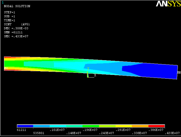
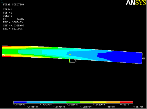
A quantitative analysis was performed based on a scale of progressive visual colors predefined by the software used (ANSYS Workbench 16.5), ranging from dark blue to red.
5. Results
Fig (15) shows a histogram of stress and maximum strain of Von Mises, we notice that the spine undergoes a concentration of maximum stresses in the thoracic region, in the order word the stresses in the thoracic vertebrae (Th3, Th4, Th5, Th6, Th7) are respectively equal to (995,68MPa, 754.61 MPa, 467.09 MPa, 483.08 MPa, 369.65 MPa) as mentioned in \ "(Fig. 17) \".
Fig 16 shows a load applied to the upper surface of the thoracic vertebra TH1 of the spinal column causes a high concentration of maximum Von Mises strains in the anterior part of vertebral bodies (red section) this is mentioned in \ "(Fig. 17) \".
On the other hand, Fig 17 shows that the posterior arch of the thoracic vertebrae (Th3, Th4, Th5, Th6, Th7) absorbed the maximum von Mises stresses, these stresses were observed on a posterior side of the spine (red contour) with respect to other components of the system of the spine. Proceeding from the fact that the Fig ( 17) and ( 16) that watches the posterior load presents greater strains within two thoracic vertebrae (Th3, Th4) which are equal to (0.29194, 0.21867), which means that the so-called vertebrae are the most stressed in the case of posterior bending.
Fig (18) shows that the posterior loading presents maximum stresses and strains concentrated in the intervertebral disc D1 that is to say between the sacrum and the lumbar vertebra L5, in the order word the \ "(Fig. 19) \" clearly shows that the loading posterior with a lever arm equal 350mm presents maximum Von Mises stresses and strains concentrated in the disc D1 and are respectively equal to (6,9797MPa, 1,7347mm / mm). We see in Fig ( 18) the intervertebral discs (D1, D15, D16, D17) absorbed the maximum stresses that equal (6,9797MPa, 4,4374MPa, 4,7858MPa, 2,7365MPa), On the other hand the posterior loading presents of maximum strains concentrated in the intervertebral discs (D1, D15, D16, D17) which are respectively equal to (1.7347, 1.0586, 1.1463, 0 66065) as mentioned in \ "(Fig. 19) \". On the other hand, \ "(Fig. 22) \" shows that the maximum von Mises stresses in the cortical bone (S1, Th12, Th5, Th1) are equal to (40,069MPa, 140.15 MPa 223.82 MPa 496, 69 MPa) as compared to other components of the system of the spine see \ "(Fig. 24) \". A loading of the posterior backpack applied on the upper surface of the thoracic vertebra TH1 of the spinal column causes a high concentration of maximum normal strains in the anterior part of the thoracic vertebra Th (red part) this is mentioned in \ "(Fig. 23) \", with regard to the said vertebra supported Von strain value set which are equal to (0,041791mm / mm) relative to the other components of the system of the spine.
The posterior load \ "(Fig. 3) \" shows clearly that the stresses and strains of Von Mises are concentrated in the two cancellous bone (Th1, Th5) and are respectively equal to (4.6282Mpa, 5.7386MPa) and (0.049594, 0.057685) this is mentioned in the (Fig 26) The posterior loading of the backpack with a 350mm lever shown that increased stresses and strains of Von Mises illustrated in the face of upper and lower articulation of the posterior arch of the thoracic vertebrae (Th3, Th4, Th5 , Th6, Th7) (red outline) \ "(Fig. 27) \", on the other hand \ "(Fig. 28) \"shows clearly legend stress and strain of Von Mises put in the thoracic region (Th3, Th4, Th5, Th6, Th7) are respectively equal to (995,68MPa, 754,61MPa, 467,09MPa, 483,08MPa, 369,65MPa) and (0.29194, 0.21719, 0.16183, 0.21867, IV.
6. Discussion
In sum, we concluded that the posterior loading is certainly an aggravating factor, and may cause long term back problems and strains of the spine, the 3D model of the spine of a child under the effect of an eccentric load and calculate by the FEM provokes stress and strains maximum of Von Mises concentrated in the intervertebral disc (D1) and are equal to (6,9797MPa, 1,7347mm / mm) as noted in the \ "(Fig. 18) \", with regard to \ "(Fig. 19, 20, 21) \" show that the intervertebral disc (D1) is the most damaged which is disc degeneration often occurs after a phase asymptomatic dehydration cracks, tearing of annulus fibrosus (D1 ), the nucleus (N1) can then along these cracks migrate into the ring thickness (D1), and cause acute or chronic back pain, If the core (N1) move around more through the ring (D1), the core can project to the posterior surface of the disc while forming a lumbar disc herniation, this hernia can complete rupture of the ring, migrate laterally into the vertebral canal, or up or down, and even exclude leaving the disk, herniated disc that can come be compressed one or more nerve roots "stuck" near the disc, causing the symptoms of pain "sciatica" when the rear seat of the thigh or "cruralgie" when the seat of pain in the front of the thigh. This justifies that the distance between the load which is the point of application of the load and the axis of the spine plays an important role in increasing stresses at the intervertebral discs.
V.
7. Conclusion
In sum, we concluded the case of posterior loading 350mm lever arm with a load 200N posterior indicate normal maximum Von Mises stresses in four intervertebral discs (D1, D15, D16, D17) and are equal to (6,9797MPa, 4,4374MPa, 4,7858MPa, 2,7365MPa) these mentioned in \ "(Fig. 18) \", on the other hand \ "(Fig. 19) \"clearly shows the elastic strain is higher in the four intervertebral discs (D1, D15, D16, D17) that are equal (1.7347, 1.0586, 1.1463, 0 66065), which justifies that the distance between the load which is the point of application of the load and the axis of the spine plays a very important role in increasing the solitation of the latter.
8. VI.
9. Global
![Fig. 1: Normal disc (top). Herniated disc (bottom) shows the gel-filled nucleus escapes through a tear in the disc annulus and compresses the spinal nerve [3].](https://engineeringresearch.org/index.php/GJRE/article/download/1506/version/100745/1-The-Effect-of-the-Eccentric-Loading_html/16198/image-2.png)
![Fig. 2: Evolutionary forms of the herniated disc. (a) back pain. (b) -crack the annulus, (c) -progression the disc material, (d) -prolapse [4]. & www.espalda.org](https://engineeringresearch.org/index.php/GJRE/article/download/1506/version/100745/1-The-Effect-of-the-Eccentric-Loading_html/16200/image-4.png)
![Fig.6: Load distribution at the disc D1 according to his state[8].](https://engineeringresearch.org/index.php/GJRE/article/download/1506/version/100745/1-The-Effect-of-the-Eccentric-Loading_html/16202/image-6.png)

![Mechanical characteristics of disc tissue [9].](https://engineeringresearch.org/index.php/GJRE/article/download/1506/version/100745/1-The-Effect-of-the-Eccentric-Loading_html/16208/image-12.png)

| ". |
| COMPONENT | NODES | ELEMENTS | Thickness |
| Cortical Bone | 961810 | 644683 | 3mm |
| Cancellous Bone | 244460 | 164441 | 3mm |
| Posterior Bone | 226389 | 132464 | 3mm |
| Cartilage endplates | 160055 | 87710 | 3mm |
| Annulus Ground Substance | 244800 | 114036 | 3mm |
| Nucleus Pulposus | 42449 | 26112 | 3mm |
| Anterior Longitudinal Ligament | 45798 | 24467 | 3mm |
| Posterior Longitudinal Ligament | 14414 | 6607 | 3mm |
| Ligamentum Flavum | 30226 | 13447 | 3mm |
| Transverse Ligament | 285328 | 131648 | 3mm |
| Inter-Spinous Ligament | 28968 | 13158 | 3mm |
| Supra-Spinous Ligament | 17833 | 8279 | 3mm |
| Capsular ligament | 51816 | 24072 | 3mm |
| Sacrotuberous Ligament | 20878 | 10128 | 3mm |
| Sacroiliac posterior Ligament | 5876 | 3280 | 3mm |
| Interosseouse Ligament | 13756 | 8306 | 3mm |
| TOTAL | 2005025 | 1178694 | 3mm |