1. I. Introduction
ne of the most important steel structure connections in this study is the connection of column to base plate because it transfers all the forces of entire structure to the foundation and it is themaximum point of axial and shear forces and some moment-rotation curves. This connection is the place of overall instability and destruction of structure specifically at the time of earthquake and it effects on the behavior of entire structure. Therefore, careful consideration of its behavior especially its seismic behavior is very important. It has been observed in some cases that the lack of proper application of design or construction caused in the destruction of structure. One particular issue which increases the importance of column base connection evaluation is the effect of various members and their features in connection. These connections are consisted of columns, plates of base plates, foundations and bolts. [1][2][3][4][5][6] This connection behavior is influenced by different parameters. The most important of these parameters can be assessed as follows:
? Dimensions and thickness of columns base ? Diameter, length and position of tie rods ? Strength of available materials included sheets, tie rods and concrete
? Geometry in the foundation ? The type of loading ? The distance between the edge of columns and base plate ? The ratio of concrete surface to sheet surface
The Classification of this connection can be done in different ways. This classification can be classified as behavioral perspective, resistance, energy dissipation capacity, failure mode and the ways of loading. Several methods and experiments by different researchers in different fields have been done for the behavior of columns base, different components and factors affecting the connection. Most of these studies have been carried for the behavior of connection in the static loading or numerical study of the connection behavior.[7-12] Today, good methods for assessing resistance and initial stiffness have been developed. But for other features such as rotational capacity, curve, there is no appropriate way to the appropriate level. If these features could be estimated accurately, significant progress had been achieved in structural design. In this study, for estimating the columns to base plate connection response, independent of the experiment results, the component-based modeling and finite element method were used. First, component-based modeling in compliance with the mechanical principles was introduced and then the moment-rotational curve has obtained. Then the sample was modeled by ANSYS finite element software and loaded by monotonic loading. The prepared samples in the laboratory of Babol Noshirvani University of Technology have been loaded under monotonic loading and the results were recorded. The results of laboratory tests have been used as a verification model. In the end, the advantages and disadvantages of two models in comparison to laboratory models were discussed.
2. II. Laboratory Evaluation
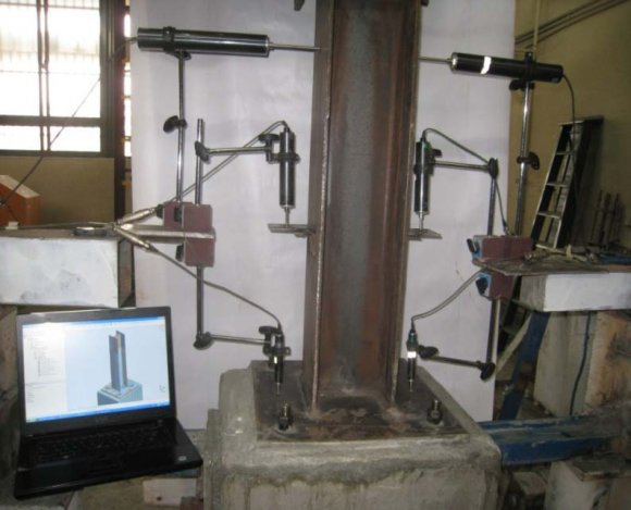
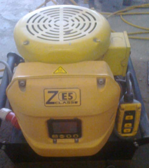
The main and common methods for determining the curve is experiment on the connections. For designing curves, bending moments were directly measured by the static loading of experimental sample and rotational angles based on the transferring of beams in comparison to depth. Seyed Mostafa Shabanian ? , Gholamreza Abdollahzadeh ? & Amir sina Tavakol ? laboratory of Babol Noshrivani University of Technology. For creating the samples, firstly, the required sample sections were prepared and drilled. In addition, the final assembly was carried out in the laboratory. Due to the uncertainty of welding in the laboratory, the required welding was carried in the factory. To investigate the behavior of real-time connection load, a node was entered to the connection increasingly. On the other words, at each stage of loading, the load on the connection was increased about certain weight which is more than before the last one. This loading continues until the connection is destroyed. The type of materials and the geometry characteristics of connection is provided in Table 1.Concrete with resistance of 282 kilograms per square centimeter was used for concrete Pedestal and tie rods was M20. 3 Eurocode for this state that buckling plate and tie rode occur simultaneously. The purpose of this design is that the plastic deformation can be seen in the plate and the bolts. Column size and the ratio of width to thickness was selected in such a way that the column buckling does not occur before plate rupture. The figure 1 shows the laboratory sample of column connection to base plate and loading device.
3. III. Component-Based Model
In the component-based modeling, at first the component connection are separated to its structural connection and the stiffness of each component was obtained. The entire stiffness was obtained through the sum of each stiffness component and their parameters were introduced by a suitable mathematical relationship. The diagram of moment-rotation curve was achieved. The mathematical model parameters must be defined in such a way that they can calculated using the material properties and geometry dimensions. The application of component base modeling was associated with the four basic steps. [13][14][15][16][17] ? Identifying the components connection ? Characterization of each component ? The combination of elements for assessing the general behavior of connection
4. ? Classification and Modeling
The main idea of this method is based on the study of zoetemeijer in 1983. In order to identify the behavior of components, they are often loaded by tensile, pressure and shear loading. The accuracy of this method depends on the accuracy of their characteristics and the method of components combination. In this method, it is assumed that component properties are completely independent of each other and therefore these characteristics can be easily achieved. The components behavior can be stated with a non-linear relationship of force-displacement. The components behavior is generally non-linear behavior, but it can be as simple as the two or three linear models. The model parameters can be obtained from the dimensions of the components and materials properties. The most important parameters in the mathematical model are design resistance, stiffness factor and deformation capacity. Understanding the factors of connection and failure associated modes is the first phase of the component method modeling. Rotation described the connection with the deformation of four sources which two of the sources located in stretching zone and two other sources placed in compression zone. It includes concrete under pressure with grout, and flange columns in the press, the plate of column base under bending and bolts under tensile. [18,19] In sum, the components of column to base plate connection are as follow:
? The pressure part (concrete under pressure and column base under bending) ? The Column ? The Tensional part (including tie rods and sheet under bending) ? The transfer part of cutting force The idea of evaluating the resistance and stiffness of base plate has been expressed by Jas part and Melchers. The regulations of Euro code 3 used this method to determine the characteristics of the components for the two connections to column and column to base plate. In the plate components, three different failures have been investigated.
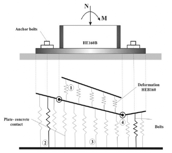
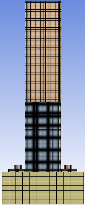
? Rupture of tie rod as the result of the top plate In order to design the rotation-moment curve which is indicated the entire node behavior, the characteristics of each component must be combined properly. To this end, appropriate mechanical and analytical models should be developed. Mechanical model provided by Jas part et al is presented in figure 4 and it is based on simulations of two-dimensional nonlinear springs. This model not only considered the nonlinear behavior of each component, but also takes the impact of the changes affecting the bending area. The model is very complicated for engineering and design applications. The applied component model in necessary to determine the design strength, stiffness and deformation capacity of this type of connection. [20,21] Figure 4 : The mechanical model of column to base plate connection It can be understood from presented models that the choice of effective area is very essential in the complexity of the final model. The reason for this is that in the process of combining components, the influence of vertical force and bending moment must be considered. The actual values of these forces are effective in the position of the neutral fiber that this case is linked to the effective area. Most suggestions for effective area is presented based on the regulation of Euro code 3. In this regulation, the stress distribution on concrete is assumed under the plate of column base. To calculate the resistance, the easiest method is the perfect plastic stress distribution. Rotational stiffness is achieved based on the model provided in the Eurocode 3. [22,23] IV. Finite Element Model Finite element method which is a subset of numerical methods is one of the most practical methods for solving the engineering problems. In 1960, the socalled finite element was firstly used by Clough to solve the problems of two-dimensional elasticity. In the finite element method, the physical issues were solved with the help of differential equations and minimizing the potential energy. By this assumption that the number of degrees of freedom is reduced a limited from the infinite degrees of freedom. In the finite element method the available continuous environment is divided into a finite number of smaller components with simple geometry and then for components of a displacement function which link the displacement of each point to shift nodes. It is assumed that due to the complex geometry of column base connections, and multi-phase environment of connections in terms of material type, in finite element models, the number of degrees of freedom is very high and relevant volume calculation is more than usual for conventional computers. The other reason which leads to the complexity is the multiplicity types of nonlinear behavior in these models. This cause that the solution engine repeatedly increase the frequency of each incremental step. In addition, in the original version, the existence of periodic load increases the influence of this issue. Therefore, it is inevitable to consider simplification for modeling. [24][25][26][27][28] In the present study, the finite element software (ANSYS) is used for modeling the column to base plate connections. SOLID components have been used to establish components connections. Contact surface friction coefficient of 0.6 is assumed to consider the frictional forces. To model the effect of pre stressing screw in modeling, PRETS179 has been used. The holes of screws were modeled 2 mm larger than the diameter of the screws. In all models by dividing the geometry of the steel mesh into the separate parts, an attempt has been made to achieve the best split lattice. The parameters used to define the size of the mesh elements were the length of elemt in near areas ( ) Areas near the connection have been modeled with the finer elements. These areas included bolts, column base plate, and end parts of the column to a distance twice the depth of the column plate which can be seen in Figure 5. Depending on the type of loading that has been done, the type of material used in hardening steel is considered isotropic which is listed in Table 3. Drucker-Prageralso used to modify the concrete behavior. This material is providing the possibility of penetrating elements of column base plate to the size of about 0.5 cm in the concrete.
5. Global Journal of Researches in Engineering ( ) Volume XVI Issue III Version I
6. V. The Evaluation of Results
Evaluation of results based on componentbased modeling. In the component-based method, modeling for a macro elements is provided by the combination of rigid rods and springs which represents the constructive engagement of the component. In this way, each of the deformation mechanisms and rigidity in specific connection is determined by testing them individually or referring to regulations. The rigidity of each components is modeled by the linear or nonlinear spring and the sum of these springs in series or parallel connections can be assembled to determine rigidity. Component-based method uses the combination of rigid elements and deformable (spring) which can indicate the source of deformation of a single component. Components usually have been modeled mechanically by the geometric properties of substances and materials. The performance of mechanical models gives a satisfactory prediction of the curve. Figure 6 shows a comparison between experimental results and the component-based model. The differences are due to the defects, mismatch and residual stress of the experimental setup which cannot be easily considered in computational models. The impact of these factors can be very high in the initial stiffness.
7. a) The results evaluation of finite element modeling
In the present study, the performance of finite element method of column connections to the based columns has been compared with the experimental results. In general, the finite element models can appear in the prediction of reliable curves. They can effectively estimate the initial stiffness and connections resistance. If all nonlinear properties of all connected materials are taken into account, it can estimate the rotational capacity of connections. This type of loading analysis is non-linear statistic model. Non-linear analysis is included the analysis of nonlinear material, geometric non-linear and nonlinear contact. In the process of the finite element model loading, load point is applied to the end of the column in the incremental linear to the finite element model. Figure 7 shows a comparison between the experimental results and finite element model. It can be seen that the stiffness of model in the initial slope of the component model is a little more than experimental model. One reason for this could be the shorter length of bolts in the numerical model which leads to the hardness of primary connection. In contrast with the increasing of load amounts, the behavior of other components will have a greater role in nonlinear connection response.
8. VI. Conclusion
In this study the behavioral curve of column connection to its based were examined through the modeling of finite element and component-based and the results of these methods were compared with the results from the laboratory. The results are presented in the following paragraph:
? By comparing the results obtained from finite element method and the results of laboratory tests it was found that in the linear region, the results are entirely consistent. But by entering to the nonlinear region, the curves are to some extent far from each other. The reasons for this difference can be the different experimental conditions in comparison to the analytical model, equipment errors used for loading, recording the results, boundary conditions, the difference in real terms other materials beam and column, and different behavior of welding elements in real models and analytical models. ? The comparison of the results indicated that there is acceptable agreement between the moment rotational curve obtained from components and laboratory tests. The differences between these two moment-rotation curves are based on some factors such as the sliding of screw and elliptical mode of the screw holes. Thus it can be concluded that the component method for parameterization the behavior of this type of connection has acceptable accuracy. In addition, by this method the number of trials and errors that have a lot of cost can be reduced.
References Références Referencias

| Tie rod | Plate thickness | plate dimention | The column section | ||||||
| ( ) cm | ( ) cm | ||||||||
| M | 20 | 20 | 50× | 50 | HEA | ? | 200 | 50× | 60 |
| Samples were design according to | |||||||||
| 120 | ||||||||||
| 100 | ||||||||||
| 80 | ||||||||||
| Title Axis | 60 | Experimental | ||||||||
| 40 | ||||||||||
| 20 | ||||||||||
| 0 | ||||||||||
| 0 | 0.01 | 0.02 | 0.03 | 0.04 Axis Title | 0.05 | 0.06 | 0.07 | 0.08 | ( ) Volume XVI Issue III Version I | |
| of Researches in Engineering | ||||||||||
| Global Journal | ||||||||||
| Yield stress | Modulus of elasticity | The abbreviated name | Corresponding part |
| 235 Mpa | 5 2.1 10 Mpa × | S235 | column base plate |
| 355 Mpa | 5 2.1 10 Mpa × | S355 | columns |
| 900 Mpa | 5 2.1 10 Mpa × | Grade10.8 | bolts |
| 25 Mpa | 4 2.5 10 Mpa × | C25 | Pedestal |
| 120 | |||||||
| 100 | |||||||
| Moment(KN.m) | 40 60 80 | Finite element Experimental | |||||
| 20 | |||||||
| 0 | |||||||
| 0.00E+00 | 2.00E-02 | 4.00E-02 | 6.00E-02 | 8.00E-02 | |||
| Rotation(rad) | |||||||
| ( ) Volume XVI Issue III Version I | |||||||
| of Researches in Engineering | |||||||
| Global Journal | |||||||
| connections | including | axialversus | moment | ||||