1. I. Introduction
uildings are subjected to two types of load (i) Vertical load due to gravity, and (ii) Lateral load due to earthquake and wind. The structural system of the building has to cater for both the types of load. The structural system of a building may also be visualized as consisting of two components (i) Horizontal framing system, consisting of slabs and beams, which is primarily responsible for transfer of vertical load to the vertical framing system and (ii) Vertical framing system, consisting of beams and columns, which is primarily responsible for transfer of lateral load to foundation. However the two components work in conjunction with each other. The old practice before 1960s had been to design buildings primarily for vertical loading and to check the adequacy of the structure for safety against lateral loads in a cursory manner. It has been established now that the design of a multi-storey building is governed by lateral loads and it should be prime concern of the designer to provide adequately safe structure against lateral loads. Further, the old buildings were having substantial non-structural masonry walls, partitions and connected staircase. These provided a significant safety margin against lateral loading. The modern buildings are having light curtain walls, lightweight flexible partitions along with high strength concrete and steel reinforcement. This reduces the safety margins provided by non-structural components. A number of structural systems have been developed in the last century for optimal transfer of lateral load. The ideal design is that in which no premium is there for lateral load i.e. the stress due to lateral loads is accommodated within the 33% increase in the permissible stresses. This design may not be possible but our aim is to reduce the premium as far as possible.
2. II. Lateral Load Resisting Structural Systems
A number of structural systems to cater the varying architectural needs are available in steel as well as concrete. Nowadays, computers are widely used for analysis of structures, as computers and software are cheaply available. For proper design of structure an understanding of the behavior of the structural system is necessary. Otherwise, the designer is bound to make mistakes in the modeling of the structure and may have erroneous designs, whatever sophisticated software he may be using. The understanding of the behavior is also necessary for the executing engineer, so that he can understand the critical actions in the structure and can take special precautions in the construction. The following sections present an overview of the behavior of various structural systems under lateral loading.
3. a) Framed structures
The frames derive their lateral load resistance from the rigidity of connections between beams and columns. The behaviour of frames is straightforward and their computer modeling is simple. A number of softwares are available for analysis of frame structures. The frames are infilled by masonry panels for the purpose of partition. These partitions are considered to be non-structural and their contribution to lateral load resistance is generally ignored. The behaviour of these panels is complex. These act as diagonal bracing members before failing and falling apart from the frame. In many cases, under severe shaking due to earthquake, these fail and fall apart before the frame is subjected to the ultimate load and that is why their contribution in lateral load resistance is not considered. However, presence of masonry panels alters the dynamic characteristics of frames and the behaviour is particularly complex when the ground storey of the frame buildings does not have masonry infills for the purpose of parking. Such buildings behave as soft ground storey. There is a sudden change in the stiffness of the building at the first floor level. This increases the storey drift and ductility demand of the ground storey tremendously and may lead to failure of the ground storey due to insufficient ductility. In such situation a safe approach to design the buildings with open ground storey for parking purpose is to increase the stiffness and ductility of the ground storey by bigger sections of beams and columns and closely spaced stirrups. In case of RC frame buildings, the floor slabs are usually casted monolithically with the frames. The floor slabs are quite rigid in their plane and are responsible for distribution of lateral load among the various frames. This action should be properly modeled in the space frame model. The modeling is particularly important in buildings having large differences in lateral stiffness of various lateral load resisting components and asymmetric buildings.
4. b) Shear wall structures
Shear wall is a slender vertical cantilever resisting the lateral load with or without frames. The behaviour of a shear wall is opposite to what its name suggests. A shear wall primarily resists the lateral load in flexure with very little shear deformations. The deformation of a shear wall is different than that of a frame. Therefore, when used in conjunction with frame, shear wall results in complex interaction with the resultant lateral load on the shear wall and frame varying in a complex manner along the height.
5. c) Braced frame system
In braced frames the lateral resistance of the structure is provided by diagonal members that together with the beams form the web of the vertical truss with the columns acting as chords. Because the horizontal shear on the building is resisted by the horizontal components of the axial tensile and compressive actions in the web members, bracing systems are highly efficient in resisting lateral loads. Bracing is generally regarded as an exclusive steel system but nowadays steel bracings are also used in reinforced concrete frames. The efficiency of bracing in being able to produce a laterally very stiff structure for a minimum of additional material makes it an economical structural form for any height of building, up to the very tallest. An additional advantage of fully triangulated bracing is that the beams usually participate only minimally in the lateral bracing action. A major disadvantage of diagonal bracing is that it obstructs the internal planning and the location of windows and doors. For this reason braced bents are usually incorporated internally along wall and partition lines and especially around elevator, stair, and service shafts. More recently external larger scale bracing extending over many stories and bays has been used to produce not only highly efficient structures but aesthetically attractive buildings. Braces are of two types, concentric and eccentric. Concentric braces connect at the beam column intersection, whereas eccentric braces connect to the beam at some distance away from the beam column intersection. These structures with braced frames increase the lateral strength and also the stiffness of the structural system and hence reduce the drift.
6. III. Cases of Study
7. IV. Objectives of Study
Comparing maximum nodal displacements, maximum relative displacement of beams reactions, vertical reactions, maximum bending moments, maximum shear forces, displaced profiles.
8. V. Results
Table1: Maximum nodal displacement comparison between three lateral load resisting systems
9. VI. Conclusions
From the above study of comparison between three common lateral load resisting systems, the following results have been obtained: 1. The nodal displacement both translational and rotational for Shear wall was least among all the three lateral load resisting systems.
10. Bending moment was comparatively lesser in
Bracing lateral load resisting system than Shear wall and Moment Resisting Frame. 3. Shear force in beams was found least in Bracing lateral load resisting system as compared to Shear wall and Moment Resisting Frame. 4. Relative displacement was found comparatively lesser in Bracing lateral load resisting system than Shear wall and Moment Resisting Frame. 5. Base reactions were higher in Shear and Bracing lateral load resisting systems than Moment resisting frames.
11. VII. Conclusion
Bracing type of lateral load resisting system is most effective in reducing displacements and forces in the members and is economical way of increasing the lateral stiffness of the building.
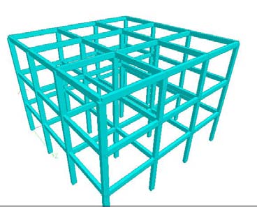
![1] Case 1: Bare Frame 2] Case 2: Shear Wall at Corners 3] Case 3: Bracings at Corners Case 1 : Bare Frame (Mrf) Case 2 : Shear Wall at Corners a) Study parameters a) Type of building: Multi Storied Building. b) Zone: V c) Type of soil: Medium d) Plan of the Building: 12X12 e) Each Bay Size: 4m f) Height of Building: 9m g) Floor to floor height: 3mts. h) Beams: 0.2mX0.35m i) Columns: 0.2mX0.35m j) Shear Wall thickness: 0.2m. k) Live load: 2kN/m2. l) Dead load of external wall as UDL: 12kN/m m) Dead load of internal wall as UDL: 6kN/m n) Damping ratio: 0.05%.](https://engineeringresearch.org/index.php/GJRE/article/download/1416/version/101390/4-Comparative-Analysis-between-Different_html/29771/image-2.png)


| Max X Min X Max Y | RESULTANT DISPLACEMENT (mm) MRF SHEAR WALL BRACED TYPES 5.893 3.731 4.209 3.612 2.391 2.384 6.895 0.257 0.213 | of Researches in Engineering | ||
| Min Y Max Z Min Z Max rX Min rX Max rY | 6.201 6.895 6.895 5.408 5.408 3.001 | 4.628 2.803 2.803 0.907 0.681 3.569 | 3.426 3.103 3.103 2.253 2.253 3.238 | Global Journal |
| Min rY | 3.001 | 3.570 | 3.238 | |
| Max rZ | 3.871 | 1.319 | 2.869 | |
| Min rZ | 5.893 | 3.731 | 4.209 | |
| Max Rst | 6.895 | 4.629 | 4.743 | |
| (only 10 beams compared) | |||||||
| MRF | SHEAR WALL | BRACED | |||||
| Beam Load cases | Max | Max | Max | Max | Max | Max | |
| FZ(kNm) | FY(kNm) | FZ(kNm) | FY(kNm) | FZ(kNm) | FY(kNm) | ||
| ELX+ | |||||||
| 1 | DL 1.5(DL+LL ELX+) | 33.683 51.298 | 0.020 | 34.080 56.799 | 5.095 7.613 | ||
| ELX+ | |||||||
| 2 | DL | 35.299 | 0.002 | 35.297 | 35.285 | ||
| 1.5(DL+LL+ELX+) | 54.711 | 58.263 | 58.258 | ||||
| ELX+ | |||||||
| 3 | DL | 0.001 | 36.914 | 36.563 | 8.088 | ||
| 1.5(DL+LL+ELX+) | 56.695 | 61.012 | 13.001 | ||||
| ELX+ | |||||||
| 4 | DL | 34.540 | 0.035 | 34.335 | 0.03 | 0.121 | |
| 1.5(DL+LL+ELX+) | 53.471 | 57.303 | 0.582 | ||||
| ELX+ | 0.264 | ||||||
| 5 | DL | 35.299 | 0.009 | 35.302 | 2.209 | ||
| 1.5(DL+LL+ELX+) | 55.143 | 58.135 | 4.289 | ||||
| ELX+ | 0.019 | 0.264 | |||||
| 6 | DL | 36.057 | 36.249 | 2.203 | 2.249 | ||
| 1.5(DL+LL+ELX+) | 55.847 | 60.555 | 4.337 | 4.395 | |||
| ELX+ | 0.067 | 0.121 | |||||
| 7 | DL | 0.001 | 32.798 | 33.296 | 0.381 | 0.769 | |
| 1.5(DL+LL+ELX+) | 52.608 | 55.628 | 0.552 | 1.385 | |||
| ELX+ | |||||||
| 8 | DL | 35.299 | 35.298 | 29.814 | |||
| 1.5(DL+LL+ELX+) | 57.175 | 58.225 | 52.913 | ||||
| ELX+ | 0.0698 | ||||||
| 9 | DL | 37.799 | 37.330 | 31.245 | |||
| 1.5(DL+LL+ELX+) | 60.992 | 62.521 | 55.980 | ||||
| ELX+ | 3.344 | 0.125 | |||||
| 10 | DL | 2.9 | 1.246 | 0.075 | 32.959 | ||
| 1.5(DL+LL+ELX+) | 58.392 | ||||||
| ( ) Volume XVI Issue I Version I | |||||
| of Researches in Engineering | |||||
| Global Journal | BEAM 1 | L/C ELX + ELX -ELX + | MRF 0.144 0.144 0.006 | SHEAR 0.058 0.058 0.037 | BRACED 0.039 0.039 0.014 |
| ELX - | 0.006 | 0.037 | 0.014 | ||
| DL | 1.032 | 0.935 | 0.085 | ||
| LL | 0.149 | 0.135 | 0.006 | ||
| WLX + | 0.088 | 0.023 | 0.032 | ||
| WLX - | 0.086 | 0.022 | 0.021 | ||
| WLX + | 0.016 | 0.027 | 0.011 | ||
| WLX - | 0.016 | 0.026 | 0.016 | ||
| 1.5(DL+LL+ELX+) 1.862 | 1.617 | 0.185 | |||
| 1.5(DL+LL+ELX -) | 1.818 | 1.608 | 0.151 | ||