1. Introduction
trend by which fine solids are changed into a fluid-like state through contact with gas or liquid or by both gas and liquid is termed as Fluidization. It is a contacting technique, which has extensive industrial applications and several Investigations concerning range of aspects of fluidization is being carried out and numerous applications have been made based on these techniques like drying, adsorption and chemical processes such as combustion, carbonization, gasification and solid-catalyzed reaction. In order to keep vast variety of review and researches to rational proportion, it has been restricted to gas-solid systems. A number of outstanding reviews have been in print on measurement techniques for fluidized beds by several researchers.
Cylindrical gas-solid fluidized beds have been working in process industries. Apart from the gas-solid advantages of fluidization in cylindrical beds, the efficiency and the quality in large diameter suffer seriously due to certain drawbacks such as channeling, bubbling and slugging behavior at gas velocity higher than the minimum fluidization velocity resulting in poor gas-solid contact. Hence studies have been done by the investigators to improve the quality of gas-solid fluidization. To overcome the above mentioned drawbacks quality techniques such as vibration and rotation of the bed, use of improved distributor and promoter [20] has been studied.
Consideration of non-cylindrical conduits, instead of a cylindrical one is considered to be an striking alternative technique for improved gas-solid fluidization by reference [9] The introduction of vibrational and rotational motion of the bed and distributors promotes turbulence in a gas-solid fluidized bed that increase the fluidization quality by minimizing bubbling, channeling and slugging but the relative demerits of the above technique is increase of pressure drop. The use of non-cylindrical conduits has been found to be more effective in controlling fluidization quality as compared to the other methods [12] Recently the use of non-cylindrical beds has begun to receive much attention for several applications because of a few advantages, like (i) the operation of the fluidizer over a wide range of superficial velocity, (ii) the possibility of fluidizing a wide range of particles of different sizes or densities, and (iii) intensive particle mixing.
Fluidized bed combustion initiated from a flame low grades of variety of fuels. One of the main rewards of fluidized bed is its ability to burn several fuels and is also characterized by following parameters i-e Sulphur removal and low Nox emissions without any particular designed DeSOx or DeNOx equipment [11]. To fluidize biomass is another complicated process Some studies have been done to determine the effect of particle size, shapes and densities of different biomass such as wood chips, mung beans, millets, corn stalks and cotton stalks on minimum fluidization velocity [2]. The effect of tubular assembly on minimum fluidization velocity has not been covered by majority of researchers and is being studied in current paper.
The purpose of this study is to determine minimum fluidization velocity for local sand and rice husk at different aspect ratios and to investigate the effect of minimum fluidization velocity in presence of tubular assembly of two different arrangements triangular pitch and square pitch having 1.2" diameter of tubes.
2. II.
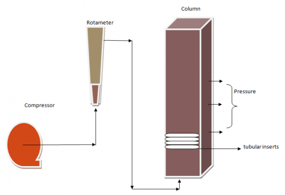
Experimental Setup 0.1211 m 2 Atmospheric Fluidized Bed has been fabricated in this study. A schematic diagram of apparatus is shown in Fig1. Rotameter is used to regulate the air flowrate having pressure of 100 psi. Spargers tubes were used as a distributor inserted beneath be for uniform mixing. Local Sand and rice husk has been used both exhibit same diameter of 149?m but different densities 1490 kg/m 3 and 567 kg/m 3 to be familiar with fluidization characteristics for materials having different densities. Tubes inserted having diameter of 1.2 inches and two different assemblies i-e triangular pitch and square pitch. Both arrangements were used on 6 inches above the distributor to keep away from trouble in air distribution.
3. Experimental Procedure
Minimum fluidization velocity was examined experimentally by observing pressure drop across the bed of 0.348m*0.348m fluidized bed reactor. The bed was packed with both solid particles (sand and rice husk) one by one and then vigorously fluidized by introducing air at 100 psi and at particular initial air flow rate to split down the internal structures. Superficial air velocity was varied and at each increment pressure drop was recorded by means of manometer installed. a) Applied equations [9,10] Î?"P/L={150(1-e) 2 /e 3 (µU)/(?dp) 2 }+{1.75(1-e)/e 3 (?gU 2 )/(? dp)
(1)
F D =Î?"P=AL (1-e)( ? p -? g )g(2)Ar= ? g (? p -? g ) gdp 3 /? (3)
Re mf = {C 1 2 +C 2 Ar} 0.5 -C 1(4)Re mf = U mf d p ? g /? g ( 5) Results and Discussion a) Effect of materials and aspect ratios Two materials having same diameters and different densities were being studied in the 0.348m*0.348m fluidized bed reactor as a bed material to understand the effect of densities on minimum fluidization velocities and it is observed that rice husk has lower density and so is the minimum fluidization velocity as compared to the local sand having higher density. As well as aspect ratio is concerned pressure drop increases on increasing bed height or aspect ratio but there is no effect of aspect ratio on minimum fluidization velocity hence minimum fluidization velocity for both the material are independent on aspect ratio. fig 5 represents the graph between minimum fluidization velocity for two different materials at three different aspect ratios. Hence at Umf pressure drop is constant so to put side by side different beds with and without inserts one should plot this against true superficial velocity as shown in Fig 14 . and showed that Umf is reduced when number of tubes inserted inside the bed.
U mf = Re mf (? g )/d p ? g (6)4. Î?"P'= Î?"p
Equations for true values obtained from reference [1] Fig 12 : Graph between true values of pressure drop and superficial air velocity for triangular and square pitch arrangements of tubes inside the bed for sand particles at 0.33m initial bed height ? Pressure drop increased as bed height incremented.
? By using tubes inside bed minimum fluidization velocity reduced.

| Year 2015 |
| 19 |
| Issue II Version I |
| ( ) Volume XV |
| Global Journal of Researches in Engineering |
| Effect of Aspect Ratio, Tubular Assembly and Materials on Minimum Fluidization Velocity in | |||||||||||
| 3D-Atmospheric Fluidized Bed | |||||||||||
| Experimental values of pressure drop of different materials at | 7.1 | m of initial bed height & 1.2''dia tubes | |||||||||
| Sr | Flowrate | Velocity | Pressure drop | Pressure drop | |||||||
| no | Q | U | Î?"P | Î?"P | |||||||
| (l/min) | (m/s) | (Cm of water) | (Cm of water) | ||||||||
| sand | Rice husk | ||||||||||
| Without | Square | Triangular | Without | Square | Triangular | ||||||
| tubes | pitch | pitch | tubes | pitch | pitch | ||||||
| tubes | tubes | tubes | tubes | ||||||||
| 0 | 0 | 0 | 0 | 0 | 0 | 0 | 0 | ||||
| 20 | 0.0027 | 9 | 9.3 | 10 | 2.8 | 3.7 | 3 | ||||
| Year 2015 | 40 60 80 100 | 0.0049 0.0082 0.0107 0.0132 | 11.5 17 22 23 | 14 22.9 24 24.4 | 12 21 24 24.3 | 3.9 4.3 5 5.9 | 4.3 5 5.7 6 | 4 4.5 5 6 | |||
| 120 | 0.0165 | 24.1 | 18 | 24.9 | 6.8 | 7 | 7.1 | ||||
| 20 | 140 | 0.0189 | 25.5 | 19.7 | 20 | 7 | 4.8 | 7.1 | |||
| 160 | 0.021 | 19.9 | 19 | 19 | 5 | 4 | 3.3 | ||||
| I e XV Issue II Version | Experimental values of pressure drop of different materials at 10 180 0.024 18.5 19 18.5 11 200 0.027 18 19.3 18 Sr no Flowrate Q Velocity U Pressure drop Î?"P (l/min) (m/s) (Cm of water) | 6.1 | m of initial bed height & 1.2''dia tc ubes 5.9 4.3 4 5.5 4 4.4 Pressure drop Î?"P (Cm of water) | ||||||||
| ( ) Volum C Global Journal of Researches in Engineering | 10 11 | 0 20 40 60 80 100 120 140 160 180 200 | 0 0.0027 0.0049 0.0082 0.0107 0.0132 0.0165 0.0189 0.021 0.024 0.027 | Without tubes 0 10 15 20 23 23.8 25.3 26 26.5 20 22 | sand Square pitch tubes 0 11 17 20.5 25 26.5 29 20 20.2 19.9 19.9 | Triangular pitch tubes 0 10 15.5 20 25 25.3 29 30.2 19.3 20.1 20 | Without tubes 0 3 4 5.5 6 6.9 7.5 4 2 2.5 3 | Rice husk Square pitch pitch tubes Triangular tubes 0 0 4 3.8 4.5 4 6 5.7 6.7 6 7 7 5 6.1 5.1 5 5 4.3 5.3 5 5 5.5 | |||
| H/D | Sand | rice husk | ||
| U mf | Bed | U mf | Bed | |
| (m/s) | weight | (m/s) | weight | |
| ( kg) | (kg) | |||
| 0.8 | 59.6 | 22.6 | ||
| 0.021 | 0.016 | |||
| 1 | 62.5 | 23.8 | ||
| 0.018 | 0.018 | |||
| 1.1 | 0.021 | 68 | 0.018 | 26. |
| Effect of Aspect Ratio, Tubular Assembly and Materials on Minimum Fluidization Velocity in | ||||||
| 3D-Atmospheric Fluidized Bed | ||||||
| of 1.2" tubes at | 7.1 | m initial bed height of rice husk particles | ||||
| of 1.2" tubes at | 6.1 | m initial bed height of rice husk particles | ||||
| Materials Particle | U mf (woi) | Re mf | Ar | |||
| density | (m/s) | |||||
| ? p | ||||||
| (kg/m 3 ) | Exp | Pred. | ||||
| Sand | 1490 | 0.021 0.015 0.12 | 165 | |||
| Rice | 567 | 0.018 0.004 0.04 62.07 | ||||
| husk | ||||||
| Symbols used |
| d p =diameter of particles [?m] |
| H=height of bed [m] |
| D=diameter of fluidized bed [m] |
| H/D=height-to-diameter ratio [dimensionless] |
| U=superficial air velocity [m/s] |
| Umf=minimum fluidization velocity [m/s] |
| ?P=pressure drop across the column [cm of H 2 O] |
| Ar=Archimedes number [-] |
| ?g= density of gas [kg/m3] |
| ?p=density of particle [kg/m 3 ] |
| g=gravitational constant [m/s 2 ] |
| ?g=viscosity of gas [Ns/m2] |
| Remf= Reynolds number [-] |
| es=voidage of sand[-] |
| er=voidage of rice husk[-] |
| ?s=sphericity of sand[-] |
| ?r=sphericity of rice husk[-] |
| U'=true velocity [m/s] |
| Î?"P'=true pressure drop[-] |
| L 1 =depth of bed with inserts[m] |
| L 2 =depth of bed without inserts[m] |
| a t =cross section area of tubes[m2] |
| a b =cross section area of bed[m2] |
| woi= without inserts |
| VII. |