1. Introduction
oad accident is rapidly increasing with the number of vehicle and with the extension of metro life. About 1.24 million deaths occurred worldwide in the year 2010 due to road traffic injuries [1], and the number of people are injured or disabled every year also in the range of tens of millions [2]. WHO, is already working with governmental and nongovernmental organizations around the world to raise awareness to avoid road traffic injuries [2].Many other organizations like, National Highway Traffic Safety Administration (NHTSA), USA, are on the pursuit of vehicle safety has led to focus attention on self-driving automated vehicles [3].Already Google got, first selfdriven automated vehicle license in Nevada, USA [4]. Still there is lot of research work needed before the first low cost automated vehicle is on the road. For this purpose, this paper demonstrates design and development of a low cost solar automatic vehicle.
The demand of fuel energy is increasing day by day due to industrialization, transportation and inhabitation. According to BP(British Petroleum)-the Global demand will rise up to 5 to 20 Mb/d (Millions of Barrels per Day) from 2015 to 2035 [5]. So renewable energy (energy from a source that is not depleted when used, such as wind or solar power) is indispensable for this crises. Renewable energy has a lot of advantages over the fuel energy, which is available abundant amount in nature with no negative effect on environment, having no solid wastes. It reduces pollution production and do not threaten the atmospheric levels. For these specific reasons, renewable energy to be used. The automatic solar vehicle is powered by solar energy and it is done by incorporating the vehicle with a solar panel.
2. II.
3. Background Study
4. Automated Vehicle
Automated Vehicle is a vehicle, which has at least one automated functions (like steering, acceleration etc.).According to National Highway Traffic Safety Administration (NHTSA), USA. At level 4, an automated vehicle will be able drive itself without a human driver [6]. The main reason for using automated vehicle is that, this technology will reduce crashes. Moreover, there will be less power consumption and pollution.
5. b) Solar Module / Panel
When groups of solar cells are interconnected and mounted together it is called solar panel or module. Like, a 12 V single solar module (panel) will contain 36 cells connected in series in a sealed weatherproof package [7]. Each solar cell in a solar module coverts light energy to electricity, so that the solar panel can be used as a power source. Because solar energy is
6. F
This paper discuss about design and development of an automated solar vehicle. The schematics were drawn by using Proteus Lite software and the components were soldered intoveroboard. It was found that the automated solar vehicle is able to move around the road automatically by using three photosensors or using photosensors and a microcontroller (PIC 16F877A).
7. a)
, available in abundance and considered the easiest and cleanest means of tapping renewable energy [8], solar panel is used in the design as a mean ofcharging the battery of automated solar vehicle. Photodetector or Photosensor is a device that can detect the presence of photons and converts optical signal to electrical signals [9]. Photodiodes operates in Photovoltaic or Photoconductive mode. In the photoconductive mode the photodiode operates in reverse bias and thus creates electric fields and increases the width of space charged region. When light falls, depending on the energy of the photon h?, electrons -holes pair are generated in the space charged region and the electric field (due to reverse bias) will swept away the e-h pairs and produces current in the external circuit [10]. In developing the solar automatic vehicle, photosensors / photodetectors are used. These photodetectors can detect black or white color, by which the vehicle can sense where it is and moves accordingly on the road.
8. d) Motor Driver
Motor driver is a device which can drive motor or motors. Motor driver is used because a motor needs high current and a motor driver, amplifies low current to necessary high current, which drives the motor [12]. In designing the solar automated vehicle L293D motor driver IC is used. L293D has two inbuilt H-bridge driver circuits to drive two motors simultaneously. It is called H-bridge because four switches are arranged such that it resembles like 'H'. Shown in figure 3.
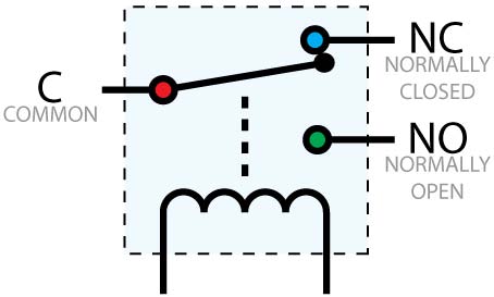
9. e) Relay
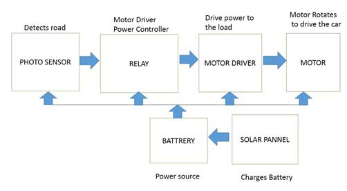
A relay is an electrically controlled electromechanical switch. It operates on the principle of electromagnet [14]. By the relay control circuit, when the relay coil is energized, the electromagnetic field of the coil forces the common switch element (moving part of the switch) inside the relay to disconnect its contact with the normally closed (NC) terminal and make connection with the normally open (NO)terminal. Otherwise, when the relay coil is not energized, the common switch element will stay atnormally closed (NC) terminal. After detection of light, the photosensors convert the light signal to electrical signal. Depending upon the electrical signal, the relay will provide isolation or electrical signal to the motor driver, the motor driver will provide necessary current to drive the motor and thus the vehicle will move around the road. The battery ensures necessary power to every components and a solar panel charges the battery.
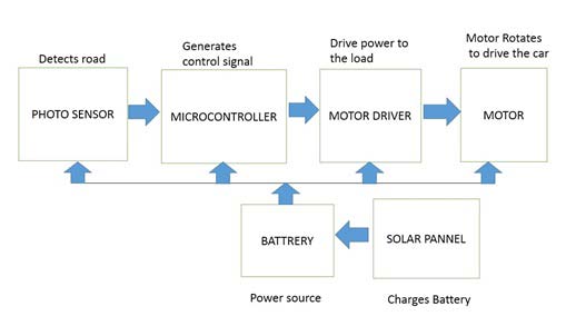
10. b) Block diagram of microcontroller based automated solar vehicle
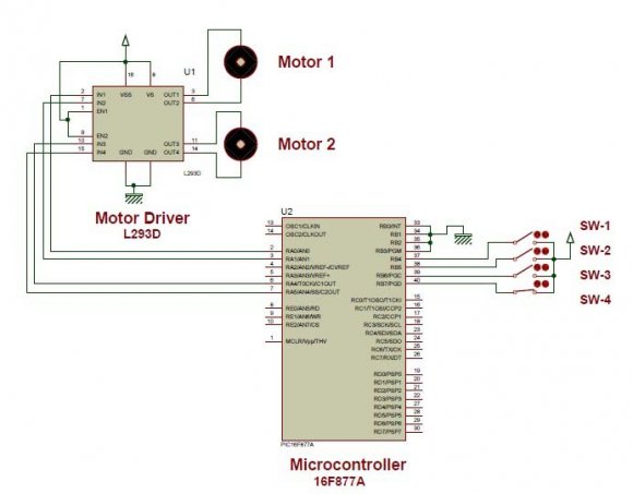
The only difference in the block diagram of microcontroller based solar automated vehicle is that instead of a relay block (in figure 5) there is a micro controller block (figure 5). The relay function is done by using microcontroller. After getting electrical signal from the photodiodes, the microcontroller sends control signal to the motor driver to drive the motor and the vehicle moves around the road.
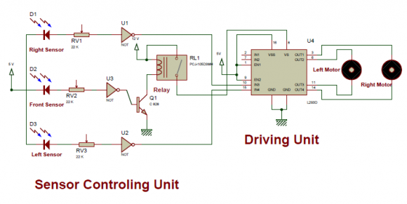
11. Schematic Diagram of Solar Automated Vehicle
the vehicle moves forward. When the vehicle needs to turn right, the left photosensor will detect white color, thus converting the white color to 1 volt, which goes through the not gate thus producing 0 volt to the input 4 (pin 15) of L293D motor driver IC. At this moment the right photosensor detect black light and covert the black light to 0 volt, which goes through the not gate thus producing 5 volt to the input 3 (pin 10) of L293D motor driver IC. Because inputting binary 01 signal to motor driver input 3 (pin 10)and input 4 (pin 15)will give 12 volt to output pin 11 and 0 volt to output pin 14,So the right motor(figure 7) will stop and the vehicle will turn to the right.If there is a left turn, then right photosensor will detect white color and the left photosensor will detect black color, producing binary 10 signal to motor driver input 4 (pin 15)and input 3 (pin 10)will give 12 volt to output pin 14 and 0 volt to output pin 11, thus stopping the left motor(figure 7) and the vehicle will turn left. But if there is obstruction, the front sensor will detect white color, convert it to 1 volt, which goes through the not gate thereby producing 0 volt at the base of transistor. Thus the transistor will remain open, the relay coil will never magnetized, then the common switch element (moving part of the switch) remain open, 12 volt power will not go L293D motor driver IC power supply (VS, pin-8), making it powerless, and thereby making both the motor stops, as a result also making the vehicle stop.
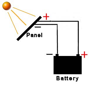
12. Battery Charging Section
A 12 volt Battery is used as power source of the solar automated vehicle. To charge the 12 Volt batterya 16 Volt, 12 Watt solar panel is directly connected(figure 9). The main purpose of using solar panel was to see driving. It is seen that, the vehicle can easily carry the weight of solar panel. Solar charge controller is not designed for this solar automatic vehicle, but it is proposed that a solar charge controller should be designed for better battery charge control.
13. Implementing Solar Automated Vehicle
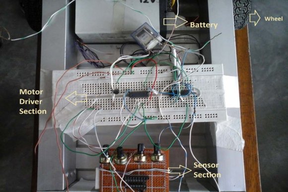
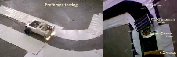
According to the schematics, at first all the equipment was soldered into veroboard and the three photosensor based solar automatic vehicle was developed. Figure 11 shows the internal circuitry of the solar automated vehicle. After assembling the prototype was tested first, then a road was constructed using black and white paper and seen that the solar automated vehicle moves around the road quite easily (Figure 12). An obstacle, was placed on the road while the vehicle was moving, and instantly the automated vehicle detect the obstacle and stop.
14. Discussion & Conclusion
It is seen that both design of solar automatic vehicle operates smoothly in the road.Furthermore, it is seen that the three photosensor based solar automated vehicle operates better than microcontroller based solar automated vehicle on the road. But the microcontroller will be able to provide more options because a real vehicle needs more options. It is seen that cost variation (From table 2) between microcontroller based and three photosensor based solar automated vehicle is less, so for further research work, a vehicle having more options it is suggested that microcontroller to be used. Though the car moves successfully on the road there are some limitations. The vehicle cannot stop until the end of the road or switched off. Also the vehicle cannot park it on the side of the road. This problem can be solved, in the microcontroller based solar automatic vehicle. There should be a switch which can turn of the photosensors, and the vehicle will have to operate manually. Left, right turn and all other options can be done using (like in figure 8) switching function. Another limitation is there is no solar charge controller, it would be appropriate, if solar charge controller is incorporated with the vehicle to function more efficiently. Despite the limitations, there are lot of advantages, like use renewable energy, safe driving, not producing any smokeand noise, very light weight, low cost etc. Still many research work is needed to bring the solar automated vehicle on the road for commercial use. Hopefully, the day is not too far away that everybody will see solar automated vehicle on the road.

![Figure 2 : Photodiode [11]](https://engineeringresearch.org/index.php/GJRE/article/download/1308/version/100661/4-Design-and-Development_html/14321/image-3.png)
![Figure 3 : H-bridge driver circuits [13]](https://engineeringresearch.org/index.php/GJRE/article/download/1308/version/100661/4-Design-and-Development_html/14322/image-4.png)
![Figure 4 : Relay [15] III. Principle of Solar Automated Vehicle a) Block diagram of photosensor based automated solar vehicle While the vehicle is on the road the black color is detected by the photosensors and if the vehicle is outside the road or there are any obstructions, white color is detected by the photosensors.](https://engineeringresearch.org/index.php/GJRE/article/download/1308/version/100661/4-Design-and-Development_html/14323/image-5.png)
![Figure 11: Internal circuit of solar automatic vehicle A video of the solar automated vehicle is uploaded to you tube website [16]. After developing the three photosensor based solar automatic vehicle a microcontroller based solar automatic vehicle was developed and tested on the road. The microcontroller based vehicle also workaccurately as the three photosensor based solar automated vehicle. Figure 13 shows the microcontroller section and the microcontroller based solar automated vehicle.](https://engineeringresearch.org/index.php/GJRE/article/download/1308/version/100661/4-Design-and-Development_html/14330/image-12.png)
| Three photosensor based solar | Microcontroller based solar automated vehicle | ||
| automated vehicle | |||
| Product Name | Cost(tk) | Product Name | Cost(tk) |
| a) Motor Driver IC | 90 tk | a) Microcontroller | 250 tk |
| b) Motor (2 pieces) | 600 tk | b) Motor Driver IC | 90 tk |
| c) Car Frame | 200tk | c) Motor (2 pieces) | 600 tk |
| d) Resistors(5 pieces) | 100 tk | d) Car Frame | 200tk |
| e) Photosensors | 50 tk | e) Resistors(5 pieces) | 100 tk |
| f)Veroboard | 30 tk | f) Photosensors | 100 tk |
| g) Battery | 600 tk | g)Veroboard | 30 tk |
| h) Solar panel | 1200 tk | h) Battery | 600 tk |
| i)Car Wheel | 150 tk | i) Solar panel | 1200 tk |
| j)Others Apparatus | 200 tk | j)Car Wheel | 150 tk |
| k)Others Apparatus | 200 tk | ||
| Total cost | 3220tk/ | Total cost | 3520tk/ |
| 40.25$ | 44.00$ | ||