1.
? Particular SHPB is developed for impact characterization of soft and light materials.
? FEM simulation is done for the critical parts of the setup.
? Hydraulic momentum arrest is provided to avoid repeated loading of specimens.
? Isolation of launching unit vibration is provided to eliminate noise signals.
? Velocity-pressure calibration is performed. Introduction n increasing demand of high strength, lightweight and soft armour material systems, especially for military applications, resulted in interesting research challenge to characterize possible materials at ballistic impacts. Nowadays FRPs and STFs are the main materials of emphasis as a solution for the mentioned challenge. Thus, their high strain rate impact behaviours need to be studied, since their properties at static loadings could not be employed for dynamic designs. For this reason, having an appropriate test setup is significant and SHPB is a potential set up to be used, Jadhav [1]. Since available SHPB setups are designed for particular challenges in terms of capacity, material type and other requirements, design customization and development of own setup for soft materials is found to be necessary.
2. Abbreviations
Thus, studying the historical background in advancements of SHPB set up starting from its first innovation up to the latest customizations is important for this particular design. According to studies in [2][3][4][5] Bertram Hopkinson primarily developed a set up called HPB in 1914 using a single bar and its modification was made in 1948 in which electrical equipment was incorporated to record the stress waves. Following this modification, Herbert Kolsky split the HPB in to incident and transmission bars in 1949 and hence the name SHPB. It is this Split Hopkinson Pressure Bar set up that has been widely used in many research studies to characterize materials at dynamic loadings. Articles [6][7][8][9][10][11][12][13] addressed a common design theory for any customization of SHPB design that could result in acceptable calibration curves and stress wave shapes. T he customization made by Robertson et al. [14] is one of the advancements that enabled the setup to test materials at strain rates ranging 50 to 104 s-1. In a more suitable approach, Haines et al. [9] followed two design phases as mechanical system and DAQ system. The mechanical system includes the launching unit which has the high pressure cylinder as a main part, the bar) and the momentum arrest. The DAQ system includes the strain gauges, oscilloscope and computer as per Guedes et al. [15].
To design the pressure bars, more emphasis should be given to the extent of stress waves to be propagated through and the following governing equations for strain rate (? ), strain (?) and stress (?) on specimen to be tested on the setup are used, Akil [2] and Song &Chen [16]:
?(t) = ? 2C b L s ? r (t), ?(t) = ? 2C b L s ? ? r (t)dt t 0 , and ?(t) = E b A b A s ? t (t)Where, C b is the elastic wave velocity in the bar, L s is the sample length and A s and A b are the specimen and bar cross-sectional areas respectively. ?? ?? , ? ?? and ?? ?? are incident, reflected and transmitted strains measured from strain gages on the bar, respectively. The pressure bars are of the same material having elastic modulus E, density ?, same cross sectional area Ab, and hence same elastic wave
velocity C b = ? E ? ? .Since the conventional SHPB setup has been designed for testing hard and metallic materials it is not suitable for softer materials like polymers and STFs. Thus, newly customized SHPB setup has to be designed depending on the nature of the planned test specimen and expected maximum impact velocity. As part of the customization process, selection of material for the pressure bars is very important as the stress wave transmission is highly dependent on it. Even though polymeric and aluminium bars are found to be suitable for the stated softer materials in terms of impedance matching as per Meng & Li [17] and Butt & Xue [18], the viscoelastic behaviour causing wave dispersion and plastic deformation of both these bar materials made them unfit for higher velocity impacts. To overcome the stated drawbacks of polymer and aluminum bars, titanium bars are employed in this particular design as it has higher yield strength with high elastic deformation behavior at impacts of extreme speeds. This study presents the mechanical design analysis of main parts of customized SHPB, where the critical ones are supported and validated by FEM simulation using Abaqus CAE.
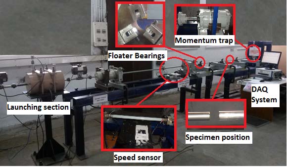
The current design has the following specifications that made it suitable to test softer materials at higher strain rates; (a) Pressure cylinder designed to accommodate extreme pressure up to 300 bar of nitrogen gas. (b) Automated control of gas filling, firing and instantaneous striker bar velocity recording. (c) Separate foundation and construction of the pressure cylinder to isolate the vibration in order not to get transmitted to the bars which otherwise would create more noise signals. (d) Complete arrest of momentum using hydraulic momentum trapping system. (e) Slender titanium alloy (ASTM Grade-5) bars with diameter of 12 mm having reasonably lower acoustic impedance suitable for high strain rate impact testing of softer materials. (f) Negligible friction between bars and bearings, by using custom designed adjustable threepoint miniature ball bearings. (g) Simplified axis alignment provisions. The overall work is presented in the following chapters.
3. II.
Materials and Methods a) Design of launching unit, the bars and momentum trapping i. Design of high pressure gas cylinder Using the design procedures of pressure vessel:
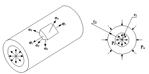
From theory of elasticity according to Budynas & Nisbett [19], a pressure vessel experiences three simultaneous principal stresses as shown in Fig. 1. The stresses over the pressure vessel wall are function of radius.
Principal stresses; ? 1 = ? t (tangential stress or hoop stress), ? 2 = ? r (radial stress), ? 3 = ? l (longitudinal stress). Thick-wall theory is considered, as it is used for any wall thickness-to-radius ratio. Cylinder geometry includes r i , r o and L (internal radius, outer radius and length respectively). Cylindrical stresses representing the principal stresses, ? t , ? r and ? l , can be calculated at any radius 'r' in the range of wall thickness betweenr i and r o .
4. Global Journal of Researches in Engineering
Tangential or hoop stress can be given as;
? t = P i r i 2 ?P o r o 2 ?r i 2 r o 2 (P o ?P i )/r 2 r o 2 ?r i 2 ;r i ? r ? r o(1)and similarly the radial stress can be given;
? r = P i r i 2 ?P o r o 2 +r i 2 r o 2 (P o ?P i )/r 2 r o 2 ?r i 2 ;r i ? r ? r o(2)However, the longitudinal stress is applicable to cases where the cylinder carries longitudinal load, such as in capped ends and in boiler vessels, valid where bending, nonlinearity and stress concentrations are not significant and can be estimated as;
? l = P i r i 2 ?P o r o 2 r o 2 ?r i 2 ;r i ? r ? r o(3)Two mechanical design cases can be considered as; Case-1: internal pressure only (P o =0)
Case-2: external pressure only (P i =0) This particular design of high pressure gas container corresponds to the first case, where P o =0; therefore, the critical section exists at r = r i , for which the hoop stress can be evaluated as;
? t (r = r i ) = ? t,max = P i r o 2 +r i 2 r o 2 ?r i 2 = P i ? 2 +1 ? 2 ?1 = P i C ti(4)Where,
? = r o r i(5)C ti = ? 2 +1 ? 2 ?1(6)are function of cylinder geometry only.
And the radial stress will become;
? r (r = r i ) = ? r,max = ?P i (which is a natural boundary condition)(7)The longitudinal stress depends on end conditions:
? l = ? P i C li , capped ends 0, uncapped ends(8)Where,
C li = 1 ? 2 ?1(9)For calculating the thickness 't' of the cylindrical shell [20], the following equation can be used.
t = P i r i SE ?0.6P i (10)Where,
5. S(allowable design stress) =
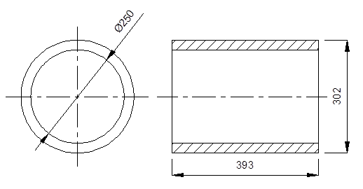
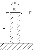
? yt FOS (11) The dimensions of the designed pressure cylinder are given in Fig. 2. The high pressure gas cylinder is subjected to thrust force generated after each firing process. This thrust force will be transmitted to its column. Fig. 3 shows the dimensions of the column and point of application of the transmitted thrust force.
6. Fig. 3 : FBD of pressure cylinder column
The maximum thrust force F t that this part can face is dependent on the net drop of the cylinder pressure after single firing.
F t = P net * A bore (12)Where, P net is the net drop of the pressure at single firing A bore is cross sectional area of the cylinder bore Using the formula for design or allowable bending stress ? b :
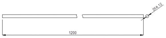
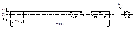
? b = M Z (13)Where, M= bending moment and Z= section modulus M = F t * L , length L of the column is fixed by the axis height of the set up to be 800 mm. Internal diameter ID of the column is fixed by the swivel of the thrust bearing seat to be 75 mm and the outer diameter OD to be calculated. To avoid buckling of the bars in between the supports, most literatures recommend that their aspect ratio (L/D ratio) should be limited to 100, however with three-point contact miniature ball bearings (floater bearings) having low coefficient of friction can be used to increase the L/D ratio. As shown in Fig. 5, the length L of the barsis maintained to be 1200 mm while their diameter is fixed by striker bar to be 12mm.
7. Design of bars and barrel
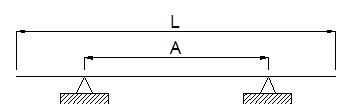
8. Position of bearing supports of Incident and Transmission bars
The number of bearing supports 'n' is fixed to be two for each bar and their position is calculated by using Airy's formula [21]. Considering the barrel as a short time pressure vessel with no welded joints; corresponding joint efficiency, E, is given as 1 and FOS is fixed to be 2.Its thickness 't' is calculated using the formula in equation ( 10) above as the internal radius of the barrel 'r ib ' is fixed by the radius of the striker bar to be 6mm.
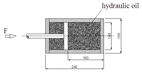
The necessary dimensions are accordingly calculated and given in Fig. 7. Selection of the right hydraulic oil should be made based on its bulk modulus or compressibility. For complete absorption of the kinetic energy KE generated at 300 bars of reservoir pressure and safe design, we assume that the total KE of the striker bar at its maximum velocity of 600m/s will be transferred to the momentum trap. From Fig. 8 it is observed that the level H of oil responsible to absorb the momentum is made 160mm and an initial volume V o is calculated as;
V o = ? * d i 2 4 * H (21)Allowing 0.2 % change in volume ?Vof the oil, bulk modulus E of the hydraulic oil will be calculated as;
E = KE ?V (22)According to the technical data in [22] the possible oil at 300 bar pressure is the petroleum based hydraulic oil with corresponding bulk modulus E of 1.6 GPa is therefore selected.
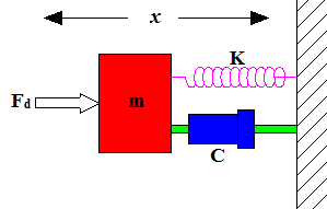
Considering the momentum trap as a mass attached with a spring and damper as shown in Fig. 9, it is modeled and the stiffness and damping coefficient are predicted as follows;
F d + Kx + Cv = 0(23)Where, F d is the maximum dynamic force to be trapped, K is the stiffness of the momentum trap, x is the maximum axial displacement of the piston, C is the damping coefficient of the momentum trap and v is velocity of the striker bar. The stiffness K is calculated using the following formula;
K = m * ? n 2 (24)Where, m is mass of the movable parts in the momentum trap (head+rod+piston), and ? n is the natural frequency.
? n = C st 2 * L t (25)where C st is speed of sound in the bars given as 5073 m s and L t is length of the transmission bar.
9. III.
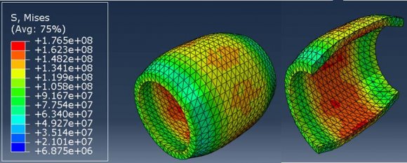
Fem Simulation of Critical Parts using Abaqus cae 6.10 a) Pressure Cylinder
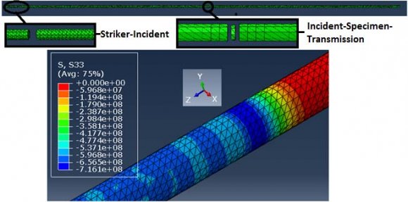
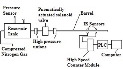
The following input data are provided to simulate the stress condition of the cylinder under maximum nitrogen gas pressure and observation of the maximum stress is taken, as shown in Fig. 10 Loading Duration = 60 ?s (set to be two times period of the wave to check for higher stress) Since each bar of the assembly could not be visually identified in a window at a time, the zoomed images of the interaction areas are displayed in Fig. 12. The first one is the interaction between striker bar and incident bar while the second one is between incident bar, specimen and transmission bar. The results of which are discussed later in the Results and Discussion section. The instrumentation of the SHPB set-up typically comprises a velocity measurement system, strain gauges, high speed strain gage input module with builtin signal conditioner and amplifier as well as voltage excitation source for powering the wheat stone bridge circuit, and oscilloscope for the display of acquired strain signals in both the incident and transmission bars. The following section discusses each of the above components of DAQ system in detail.
10. i. Velocity Measurement System
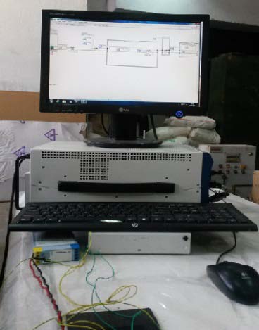
The main purpose of the velocity measurement system is to determine the impact velocity of the striker bar. It comprises of two IR (Infra-red) sensors, KOYO PLC and high speed counter module (HO-CTRIO-2). As soon as the striker bar is triggered, it passes in front of the IR sensors within a fraction of second. Consequently, pulse state and stop is registered in the PLC. The function of the high speed counter module is to determine the time duration between the consecutive pulse start and stop. By knowing the distance between the speed sensors, the impact velocity of the striker bar is calculated. The schematic of the velocitymeasurement system is illustrated in Fig. 13. This system comprises of the strain gages, signal conditioner cum amplifier and data acquisition (DAQ) system. The selection of appropriate DAQ system is solely based upon the required sampling frequency (f s ) i.e. number of samples taken per second. The sampling rate of the DAQ system must satisfy the Nyquist criterion [23], which states that the signal must be sampled at a frequency which is greater than twice the highest frequency component of interest in the signal, otherwise, the high frequency content will alias at a frequency inside the spectrum of pass-band. The specific DAQ system used in this setup is based on NI PXIe supported by Lab view software. Fig. 14 shows the photograph of the DAQ and analysis system including the strain input card and the monitor. Sampling rate f s of the DAQ system
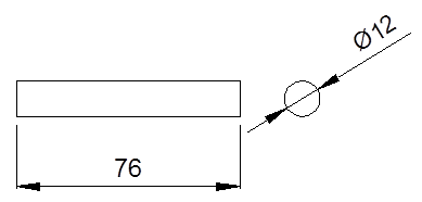
T = ?/C(26)Where, ? is the wave length and C is the wave speed with in the pressure bars. The wave length ? is two times the length of the striker bar which comes out to be 0.152m (2*0.076m). Period T is calculated to be 30 ?s and the subsequent maximum wave frequency f max will be 1/T, which is nearly 34 KHZ. Thus, sampling rate of DAQ system, according to Nyquist criteria; f s >2f max , should at least be 70 Kilo samples per second (>2*34 KS/sec).
11. Wheatstone Bridge Configuration
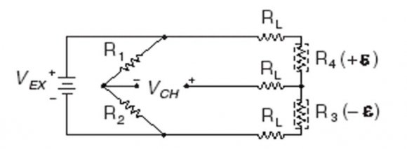
Two active strain gages were mounted diametrically opposite on the bars, thus constituting Half Bridge Type II configuration. In Fig. 15, R 1 and R 2 are the half bridge completion resistors, R 3 is the active strain gage element measuring the compressive strain (-?) and R 4 is the active strain gage element measuring the tensile strain (+?). This bridge configuration measures purely axial strain while rejecting the bending strain. The strain gage output voltage was converted to corresponding strain units by using the following equation.
Strain (?) = ( ?2???? ???? ) * (1 + ?? ?? ?? ð??"ð??" )(27)Where, V r (the voltage ratio)
= ?? ???? (???????????????? )? ?? ???? (???????????????????? ) ?? ????(28)V EX is the excitation voltage,V CH is the measured signal voltage,GF is Gage factor of the strain gages and R L& R g are lead resistance andnominal strain gage resistance, respectively.
12. e) Fabrication and Installation
Fabrication of the designed SHPB parts, their assembly and the total installation is thereby accomplished. The total setup assembly contains different mechanical, electrical and electromechanical parts as tabulated in Table 1 below. ? High pressure gas reservoir (300 bar capacity)
? Reservoir vent needle valve (250 bar capacity)
? Reservoir column
? Swivel
? Nitrogen gas supply pressure cylinder (accumulator)
? High pressure nipples (400 bar capacity)
? High pressure Union pipe joints (250 bar capacity)
? Barrel support block-1 (large)
? Barrel support block-2 (small)
? Barrel clamps (2)? Cross channels (2)
? Bearing supports (4)
? Floater bearings (4)
? C-clamps (18)
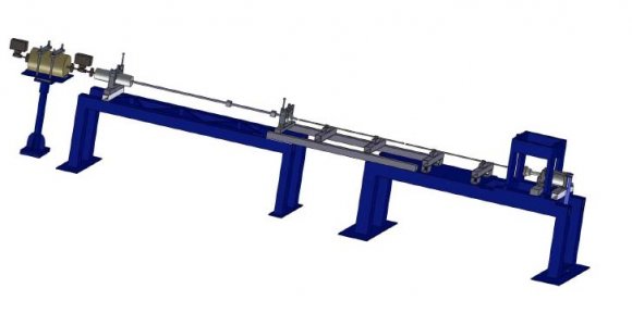
? Hydraulic momentum trap The solid model and photograph of the developed setup are shown in Fig. 16 and Fig. 17 respectively, which is in effect developed from scratch and will give an idea to others to create it from a junk yard.
?13. Results and Discussion
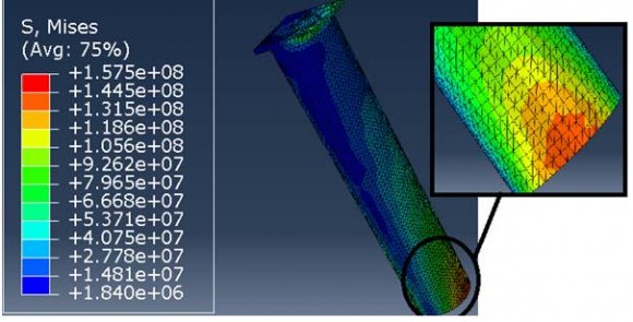
From the start of the design, assumptions of perfect gas law and adiabatic expansion were considered to make use of maximum pressure energy for safe design of the parts of the setup. The maximum pressure of nitrogen gas with in the cylinder which is 300 bar is considered throughout the entire design of each component part. Accordingly, every part of the setup is shown to be safe against the maximum applied stress. The main parts are summarized and listed in Table 2 for comparison of their strength with the maximum possible stresses obtained in FEM simulation as well as analytically. As presented in Table 2 above, the maximum possible stresses in each part as a result of design and simulation are reasonably close to each other and less than the corresponding yield strengths, which shows a safe design, however, the stress in pressure barsis quite close to the yield strength and may require continuous observation of their ends for any plastic deformation.
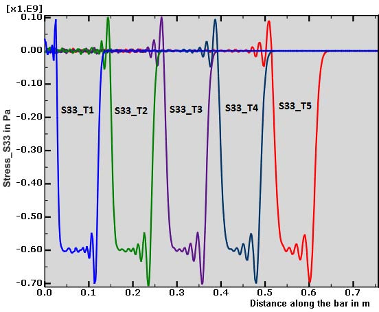
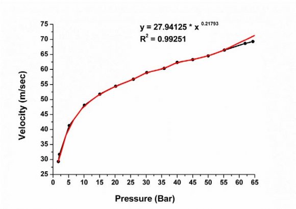
The one dimensional stress S-33 propagation along the axial direction (Z-axis) of the pressure bars is shown by post process in Fig. 18. For visualization purpose, around half the length of the incident bar is taken and the graph is displayed in five even and successive step time frames namely S33_T1, S33_T2, S33_T3, S33_T4 and S33_T5. Since the time period is set to be 100?s, each step frame occurs at every 20 ?s. It can be observed that the maximum stress on the pressure bars during such a very short loading duration is a compressive stress just exceeding 700 MPa in all the time frames. The exact value of this maximum stress can be seen in Fig. 12and Only one available paper by Haines et al. [9] presented the velocity-pressure curve of SHPB having curve fitting equation of ?? = 7.9507?? 0.2387 . In this work the curve fitting equation shown in the above graph is about 3.5X steeper. That means the velocity of the striker bar of this design is 3.5 times more at the same firing pressure. Moreover, the regression parameterR 2 is close to one which indicates consistency of the nitrogen gas expansion, negligible gas leakage through the joints, proper propelling barrel length and size of striker bar.
14. V. Conclusion
Development of particular SHPB set up of length 6.5m, height 1.2m and width of 0.56m is done after necessary design analysis and overall customization in house. This set up mainly focuses for high strain rate impact characterization of soft and light armor material systems like polymers and FRPs. Parts of the setup are designed for the maximum firing pressure of 300 bar with slender titanium bars of 12 mm diameter to help the assumption of one dimensional stress wave propagation theory. The launching unit is made separated by foundation from the bars table to protect the vibration noise signals not to be transmitted to the pressure bars. Mechanism for floater bearings is also developed to reduce the coefficient of friction which could happen between the bearing-bar interactions. A hydraulic momentum trap is provided to avoid repeated loading of test specimens so that the specimen could further be examined by subsequent tests like scanning electron microscopy. The maximum stresses on the critical mechanical parts of the setup; the cylinder, column and bars were cross checked with the FEM simulation results and compared with its corresponding yield strengths, hence safe design of the setup is observed. The velocity-pressure calibration graph achieved in this design shows that the velocity of the striker bar at a particular pressure is about 3.5 times more than the one presented in previous works. Testing of polymers and composites is in progress using this newly developed setup.
VI.

| List of Split Hopkinson Pressure Bar Parts | |
| Mechanical parts | Electrical and Electromechanical Parts |
| ? Base tables | |
| Strength and Stresses | Pressure Cylinder | Column of Cylinder | Pressure Bars (Ti6Al4V) |
| (AISI4130, steel) | (AISI4130, steel) | ||
| Yield Strength(ð??"ð??" ?? ) | 460 MPa | 460 MPa | 830 MPa |
| Max. Stress (by design) | 160.5 MPa | 230 MPa | 796.2 MPa |
| Max. Stress | 176.5 MPa | 157.5 MPa | 716 MPa |
| (bysimulation) |
| as 716MPa |