1. INTRODUCTION
rotection system's main function is to clear faults from the power system at high speed to ensure safety, minimize equipment damage and maintain power system stability [2]. Protection of power systems requires an understanding of system faults, their detection, and safe isolation of the faulted device. By taking an inventory of all the essential electrical loads and doing a basic electrical load evaluation [2], an idea regarding how much power our system needs to produce has been obtained. We are also aware about the power fluctuation situations also that means what voltage minimum / maximum we are getting from the A.C supply mains. In doing this project we would be using concepts of microcontrollers, GSM network and GUI of MATLAB.
2. II.
Fault Types and Protection a) Single-Line-to-Ground Fault A short circuit between one line and ground, very often caused by physical contact, for example due Author ? ? ?: Student, Electrical and Electronic engineering department, AIUB, Dhaka, Bangladesh 1. e-mail: [email protected] Author ?: Faculty, Electrical and Electronic engineering department, AIUB, Dhaka, Bangladesh 3. to lightning or other common means. The single line to ground fault can occur in any of the three phases [1]. However, it is sufficient to analyze only one of the cases. A short circuit between lines, caused by ionization of air, or when lines come into physical contact [1], for example due to a broken insulator. For a Line-to-line fault, the currents will be high, because the fault current is only limited by the inherent (natural) series impedance of the power system up to the point of faulty (refer Ohms law). Transformers are a critical and expensive component of the power system. Due to the long lead time for repair of and replacement of transformers, a major goal of transformer protection will restrict the damage to a faulted transformer & also protect it from thieves to avoid long term area blackouts. The comprehensive transformer protection provided by multiple function protective relays is appropriate for critical transformers of all applications [2]. Organized theft of electric transformers from live transmission lines is widespread throughout the country making power distribution agencies and consumers counting losses in several millions of BDT and great sufferings. In the last 10 years, electric transformers worth BDT 2000 Million had been stolen. So, for an improved power system stability and efficiently innovative technology, a micro controller based protection system should be achieved to protect transformers.
3. e) Lower Voltage
Low voltage is a relative term, the definition varying by context. Different definitions are used in transmission and distribution line, and in the electronics industry. Electrical safety codes define "low voltage" circuits that are exempt from the protection required at higher voltages. These definitions vary by country and specific code. Lower voltage is defined as incoming line voltage at the point of use which is smaller than the Public Service Commission's mandated legal limits; and/or smaller than the voltage ratings of the connected equipment. Lower voltage is considered a safety hazard by all industry standards and can cause premature failure of connected equipment. Devices could be damaged by lower line voltage.
4. f) Over Voltage
Overvoltage is defined as incoming line voltage at the point of use which is greater than the Public Service Commission's mandated legal limits; and/or greater than the voltage ratings of the connected equipment. Overvoltage is considered a safety hazard by all industry standards, and can cause premature failure of connected equipment. Overvoltage has been a widely known industry problem for many years, but it is not generally understood by many who have to deal with it. Power companies have been unable to control it adequately. Overvoltage occurs most often during severe cold winter weather for the following reasons: (1) Inadequate size of power distribution systems; (2) slow reaction time for power company's distribution systems to regulate voltage during extreme load variations; and (3) abrupt reductions of loads III.
5. Block Diagram Arrangement
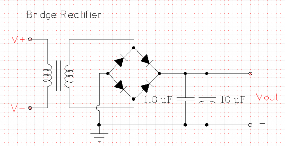
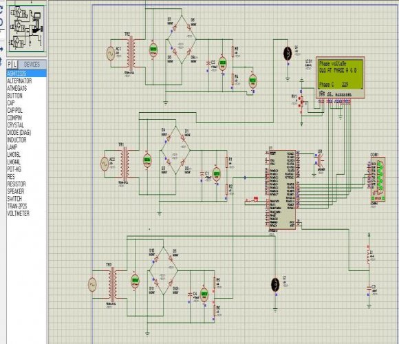
In figure 4, the basic arrangement of the implemented project can be found. An AC power source is required for powering major appliances but almost all electronic circuits require a steady DC supply. A simple rectifier circuit described in this project converts the input from AC source to DC voltage. Firstly, the AC input from mains is stepped down to a lower value of voltage. This AC supply is then passed through a rectifier circuit to remove the negative cycle of AC waveform. The resulting signal is then filtered to get the DC output. The major part of the circuit is connected to the secondary coil of the transformer which is comprised by diodes and capacitor. While the diodes act as a rectifiers, capacitor filters out the DC component from the circuit.
6. Hardware Implementation
In reference to figure 4, the transmitting and receiving side can be described as follows: a) Transmitting Side Heart of the project is the microcontroller ATMEGA 16. In general the normal distribution phase voltage is 220 V, in this project we used a step down transformer 220/12 V for converting the phase voltage from 220 V to 12 V. a bridge rectifier has been used for converting the 12 V ac to 12 V dc; after that, applied voltage divider converts the 12 V to 5 V because the microcontroller works at maximum 5 V. By this process the three distribution phase is connected into three microcontroller pins and the power transformer is connected by a narrow wire between 2 pins of the microcontroller. At cases, when the distribution side is in load shedding protection of transformer must be ensured, which is why the microcontroller power is given from an external power source (5 V battery) backup and also the GSM module power is given from external power source(9V battery) because GSM module consumes lots of power. GSM module communicates with atmeg16 through UART. RXD of GSM module is connected with TXD of atmega16 and TXD of GSM module is connected to RXD of atmega16.
7. b) Receiving Side
In receiver circuit another GSM Modem is connected with PC via USB-To-Serial converter. The GUI in MATLAB software has been is used such that it will read the message and the data will save it in an excel file and it will show a graph according to the data by using the interface. If any fault occurs, it is also capable to generate an alarm and a fault message box according to the fault. The communication protocol is UART and baud rate is 9600 [4].
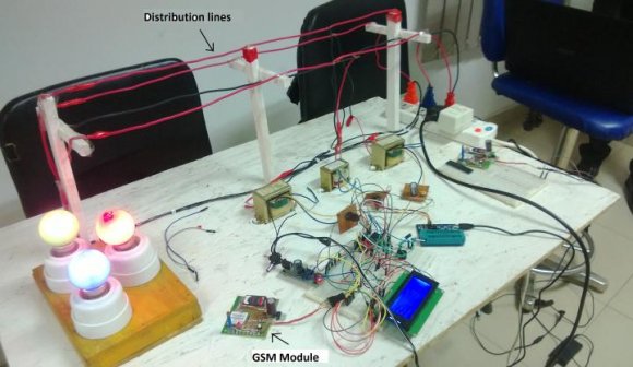
In view of the descriptions above, the implemented hardware can be found in figure 10. As viewed from figure 10, the system was found to be balanced three phase system. In figure 11, the corresponding representation appears in the LCD display with the phase voltages in all the phases to be around 219 V. The view from GUI interface is also shown in figure 12. VI.
8. Future Prospects
In view of a wide range of possibilities on the basis of microcontroller based protection system, a few has been depicted below: a) Fault detection of a wind turbine. b) GPRS based network using internet for tracking transformer. c) Improvements to human-machine interface d) Improvements in computer-based protection of Industry automation e) Long distance Data transmission.
9. VII.
10. Conclusion
Microcontroller and GSM based protection system is a reliable technique for monitoring and controlling the electric distribution system, the microcontroller works up to 100 ?C temperature. For long distance data transmission, GSM technology is a reliable and robust one. Any kind of fault occurring in the distribution system results the GSM modules to send instant messages automatically to the base station. Frequent fault occurrence can be a problem; in this case the cost of sending sms will increase resulting in account recharge in the GSM SIM number. This can be sloved in mutual agreement with telecom companies in Bangladesh (such as GP, Airtel, Banglalink, etc,). Nonetheless, GSM based microcontroller protection system will serve as a reliable, easy and cost effective solution for monitoring and controlling the electric distribution system.