1.
Abstract-This study analyzed theoretically the temperature distribution and energy storage ability of a simultaneous charging and discharging concrete bed Storage System. This was achieved by first modeled a single spherical shaped concrete which was used to represent a sequence of points along the axis of the beds.
A one dimensional finite difference formulation was used in modeling the single spherical shaped concrete material, where heat conduction to neighboring spherical concrete was ignored.
Using this assumption reduced the spherical shaped concrete model to that of an isolated sphere in cross flow, where the total surface area of the sphere was exposed to convection. The thermal properties of the materials within the bed accounted for temperature dependence.
Comparisons were made between charging and discharging mode of the storage system for air flow rates of 0.0094m 3 /s, 0.013m 3 /s, and 0.019m 3 /s. It was discovered that the difference of the temperature response between the charging and fluid to solid heat transfer process at the initial period of the packed bed was large and the heat recovered by the cool air flowing inside the copper tube was fairly high (larger inlet-outlet temperature difference compared with the later period indicates larger heat recovery).
The energy storage efficiency was also analyzed and it was discovered that spherical shaped concrete of 0.11m diameter has the highest storage efficiency of 60.5% at 0.013 m 3 /s airflow rate.
Keywords: thermal analysis, concrete-bed, charging, discharging, storage efficiency.
2. I.
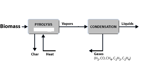
I eat transfer in concrete beds is used to describe a variety of phenomena, namely: (1) the convective heat transfer from the walls of the concrete bed to the fluid; (2) the convective heat transfer from the particles to the fluid flowing through the bed, which can be referred to as the fluid-particle mode; (3) the conduction heat transfer from the walls of the bed to the particles constituting the bed; (4) the conduction heat transfer between the individual particles in the bed; this can also be referred to as the particle-particle mode; (5) radiant heat transfer; and (6) heat transfer by mixing of the fluid (Adeyanju and Manohar 2009). These modes are described schematically in Figure 1.0. The fourth mode, namely the conduction between the particles, can be further subdivided into the axial and radial directions. Moreover, at high temperatures heat transfer by radiation will also be an important mode. In many industrial applications, it is found that two or more of the modes cited above take place simultaneously. For example, the conduction between the particles may be affected by the convection between the particles and the fluid. This interaction among the different modes is one of the main reasons for the difficulty in correlating the total heat transfer and analyzing the experimental data in this field (Balakrishnan and Pei 1974).
This study analyzed theoretically the temperature distribution and energy storage ability of a simultaneous charging and discharging concrete bed Storage System.
3. II.
4. Review of Literature
The first work on heat transfer in packed beds was published by Anzelius et al. (1926), although Schumann (1929) is usually the first reference cited in most literature (Adeyanju and Manohar 2009). Each of them made a number of simplifying assumptions and solved the heat transfer equations for an incompressible fluids passing uniformly through a bed of solid particles with perfect conductivity. The derived heat transfer equations were:
( ) ( ) ( ) , 0 - , 0 - 1 - - s s Y Z n n Y Z n n s s T T e Y M yz e Z M T T ? ? ? = ? = ? (1) ( ) ( ) ( ) ( ) - ,0 , 0 - 1- - f s Y Z n n Y Z n n f s T T e Y M yz e Z M yz T T ? ? ? ? ? ? ? =? = ? ? ? ? ? (2)Where T is the temperature (of fluid and solid) and Y and Z are dimensionless quantities. The solutions of these equations were presented in graphical form, called Schumann curves. Thus to evaluate volumetric coefficients of heat transfer using these curves, it was only necessary to measure exit air temperature and the bed temperature. These curves could be used to evaluate the heat transfer coefficients for a given packed bed undergoing heat exchange with a fluid provided the following conditions which were the simplifying assumptions made by Schumann were satisfied:
1. The solid particles were so small or have such a high thermal conductivity that no temperature gradients exist within the solid particles. This means that the solids offer a negligible resistance to heat transfer. 2. The resistance to heat transfer by conduction in the fluid was also negligible. 3. The rate of heat transfer from fluid to solid or vice versa at any point in the bed was directly proportional to the average temperature differential between them at that point. 4. The densities of solid and fluid and other transport properties were independent of temperature.
Upholding the above conditions, Furnas (1930) extended the Schumann curves to wider coverage temperatures. He also postulated an empirical relation for the evaluation of the heat transfer coefficient as shown in equation (3):
Where, h v is the volumetric heat transfer coefficient. B is a constant dependent on the bed material, G is the mass velocity of the fluid, T is the average air temperature, d p is the particle diameter and ? is the porosity.
Saunders and Ford (1940) used dimensional analysis to derive correlations to calculate heat transfer coefficient. The work was, however, limited to spheres and cannot directly be applied to other geometries of solid particles. Kays and London (1964) presented another correlation for evaluating heat transfer coefficient between gases and randomly packed solid spheres. Using the Colburn j-factor, the correlation was given as: This was evaluated for 8mm <d p < 33mm; 50 < Rep 500 and temperature range of 311K to 394K. They also concluded that the temperature of the entering air had no appreciable effect on the coefficient. Leva (1948) determined heat transfer coefficient between smooth spheres of low thermal conductivities and fluids (air and carbon dioxide) in packed beds and tubes of 50.8 and 6.4mm diameters, respectively. The ratio of particles to tube diameters was varied from 0.08 to 0.27; gas flow rate was of Reynolds number range 250 to 3,000. Correlation of film coefficient was found to be:
4.6 0.7 3.50 Dp DpG Dt µ t k h e D ? ? ? ? ? ? ? ? ? = ? ? ? ? (6a)By approximation, this reduced to ( ) ( )
0.40 / / 0.7 t h k D DpG µ = (6b) 0.7 Or, 0.4 N Re = (6c)Maximum film coefficient was predicted and verified at a value of Dp/Dt equal 0.153. Riaz (1977) and Jefferson (1972) studied the dynamic behavior of beds undergoing heat exchange with air using single and two phased modes. By incorporating factors of axial bed conduction and intraparticle resistance, which Schumann ignored, the heat transfer coefficients were evaluated and found to be 1 + Bi/5 times smaller than those predicted using Schumann curves.
Ball (1958), Norton (1946), Meek (1961), Bradshaw and Meyers (1963), Harker and Martyn (1985) and also, Bouguettaia and Harker (1991) have all researched on various packed beds using air and other gases as fluids and have developed correlations involving the heat transfer coefficient.
5. III.
6. Methodology a) Heat Transfer Model for a Spherical Shaped Concrete Packed Bed
A numerical heat transfer model was developed for the spherical shaped concrete packed bed.
This was achieved by first modeled a single spherical shaped concrete which was used to represent a sequence of points along the axis of the beds.
A one dimensional finite difference formulation was used in modeling the single spherical shaped concrete material, where heat conduction to neighboring spherical concrete was ignored.
Using this assumption reduced the spherical shaped concrete model to that of an isolated sphere in cross flow, where the total surface area of the sphere was exposed to convection. Also, the thermal properties of the materials within the bed accounted for temperature dependence.
7. b) Finite Difference Formulation of a Single Spherical Shaped Concrete Material
Since conduction to other spherical shape concrete has been neglected, the geometry allows the concrete to be reduced to one dimension along its radius.
To model this numerically, a finite difference approach was employed (Lanz 1998). For this approach, the spherical shaped concrete can be characterized by three different nodal equations:
(i) a general, interior node (ii) the center node (iii) the surface node All exposed to convection as shown in Figure 2.0.
For the general and interior node within the spherical shaped concrete model, the conduction equation for T (r,t) is:
( ) 2 , 2 1 c c c r t T T C K r q t r r r ? ? ? ? ? ? = + ? ? ? ? ? ? ? ?(7)Where C c = Specific heat of concrete c K = Thermal conductivity of concrete q = ? Heat generation And this equation was represented in finite difference form.
The specific heat, thermal conductivity, and the heat generation, are temperature dependent and varied with the temperature along the radial direction. Multiplying equation ( 7) by r 2 and integrating both sides of the equation from r n -Î?"r/2 to r n + Î?"r/2 resulted to:
( ) 2 2 2 2 2 2 2 2 2 , r r r n n n r r r n n n r r r c c c r t r r r T T C r dr K r dr r q dr t r r ? ? ? ? + + + ? ? ? ? ? ? ? ? ? ? ? = + ? ? ? ? ? ? ? ? ? ? ? (8)Since the specific heat is not as strong a function of temperature as the thermal conductivity, it was assumed constant with respect to r, and thus brought outside the integral.
By evaluating the integrals in equation ( 8) and representing the derivatives in finite difference form using the fully implicit method gives: Also, W n = W at
2 2 2 2 3 3 1 2 2 3 r r n n r r n n r r Z Z n n n n c c c r r r r T T C K rdT q r dr t ? ? ? + + + ? ? ? ? ? + ? ? ? ? ? ? = + ? ? ? ? ? ? ? ? ? ? ? ? ? ? (9) 2 2 2 2 3 3 1 2 3 2 3 2 3 r r n n r r n n r r Z Z n n n n c c c n r r r r T T K r dT r C q t r ? ? ? + + + ? ? ? ? ? + ? ? ? ? ? ? ? ? ? ? = + ? ? ? ? ? ? ? ? ? ? ? ? ? ? ? ? ? ? ? ? ? (10) ( ) ( ) 2 2 3 3 1 1 1 2 1 3 3 1 1 2 1 3 3 r n r n Z Z Z Z n n n n n n c c n c n r Z Z n n n n n n c n r r r T T T T C K r t r r r T T K r q r ? + ? + + ? + + ? ? ? ? ? + + + + + + ? ? ? ? ? ? ? ? ? ? = ? ? ? ? ? ? ? ? ? ? ? ? ? ? ? ? ? ? ? ? ? ? ? + ? ? ? ? ? ? ? ? ? ? ? Year 2014 ume XIV ( ) 1 n + ( ) 1 n ? ( ) n r r ? 2 n r r ? ? ? + ? ? ? ? 2 n r r ? ? ? ? ? ? ? ?1 Z n T + (12) 1 1 , , 2 Z n n K T K and K + + + ? ? + ? ? = at 1 Z n T + (13), 2
n n r also r r
+ ? = + (14) 2 n n r r r ? ? = ?(15)Equation ( 11) can be rearranged and solved for plus a known quantity which resulted to:
( ) ( ) 2 1 1 1 1 3 3 2 3 3 1 1 1 3 3 3 3 3 3 3 3 Z Z Z Z n c n n n n n c c n n Z Z n c n n n n n n n n n n K r T T T T C t r r r K r r r T T q r r r r r ? + + + ? ? ? + ? + ? + ? + + + + + + ? ? ? ? ? ? ? = ? ? ? ? ? ? ? ? ? ? ? ? ? ? ? ? ? ? + ? ? ? ? ? ? ? ? ? ? ? ? ? ? (16) ( ) ( ) 2 1 1 1 1 3 3 2 1 1 1 3 3 3 3 Z Z Z Z n c n n n n n c c c c n n Z Z n c n n n n n n K r T T T T C C t t r r r K r T T q r r r ? ? + + + ? ? ? + ? + + + + + + ? ? ? ? ? = ? ? ? ? ? ? ? ? ? ? ? ? + ? ? ? ? ? ? ? (17)Multiply equation ( 17) by Î?"t and divide by ? c C c resulted to:
( ) ( ) ( ) ( ) ( ) ( ) ( ) ( ) ( ) ( ) 2 1 1 1 1 3 3 2 1 1 1 3 3 3 3 3 n c n Z Z Z Z n n n n c m c m n n n c n Z Z n n n c m c m c m c m n n K r t T T T T C r r r K r t tq T T C C r r r ? ? ? + + + ? ? ? + ? + + + + + + ? ? ? ? ? = ? ? ? ? ? ? ? ? ? ? ? + ? ? ? ? ? (18) ( ) ( ) ( ) ( ) ( ) ( ) ( ) ( ) ( ) ( ) ( ) ( ) ( ) ( ) ( ) ( ) ( ) ( ) 2 1 1 1 3 3 2 2 1 1 3 3 3 3 2 3 3 3 3 3 3 3 n c n Z Z Z n n n n c m c m c m c m n n n n c n c n Z Z n n c c m c m m c m n n n n n c n c m c m n n K r t tq T T T C C r r r K r t K r t T T C r r r C r r r K r t C r r r ? ? ? ? ? + + + ? + ? + ? + ? + ? ? ? + ? + + + + + ? ? ? ? ? ? ? ? ? + = ? + ? ? ? ? ? ? ? ? ? ? ? ? ? ? ? ? ? ? ? ? ? ? + + ? ? ? ? ? ? ? ? ? ? ? ? ? ? ? ? ? ? ? ? ? ? ? ? ? ? ? ? 1 1 Z n T + ? ? ? ? ?(19)Collecting the like terms from equation (19) yielded:
( ) ( ) ( ) ( ) ( ) ( ) ( ) ( ) ( ) ( ) ( ) ( ) ( ) ( ) ( ) 2 1 1 3 3 2 2 1 3 3 2 3 3 3 3 3 1 3 n c n Z Z n n n c c m c m m c m n n n n c n c n Z n c m c m n n n c n c m c m n n K r tq t T T C C r r r K r K r t T C r r r K r t C r r r ? ? ? ? ? ? + ? ? + ? + + ? + + + ? + ? + ? ? ? ? ? ? ? ? ? ? ? ? ? + = + ? ? ? ? ? ? ? ? ? ? ? ? ? ? ? ? ? ? + ? ? ? ? ? ? ? ? ? ? ? ? ? ? ? ? ? + ? ? ? ? ? ? ? ? ? ? ? ? ? ? ? ? ? ? ? ? ? ? ? ? ? ? ? ? ? ? ? ? ? ? ? ? ? ? 1 1 Z n T + + ? ? ? ? ? ? ? ? ? ? ? (20)This resulting equation is valid for any general, interior node within the spherical shaped concrete 0 <r n < R.
At the center node, where r n = 0 the temperature profile is axisymmetric, and 0, T r ? = ? when r= 0 thus, the temperature on either side of the node is equal.
1 1 1 1 Z Z n n T T + + ? + = ( ) ( ) , c n c n likewise K K ? + = ? Equation (20) simplified to: ( ) ( ) ( ) ( ) ( ) 1 1 1 2 6 Z Z Z n n n n c n c c m c m m c m tq t T T K T C C r ? ? + + + + ? ? ? ? ? ? ? + = ? ? ? ? ? ? ?(21)This occur at r n = 0.
This simplified form of equation ( 20) was used to represent the center node.
The conduction through the surface of the spherical concrete is equal to the convection at the surface.
( )
, C r R at r R T K U T T r = ? = ? ?? = ? ? ? (22)However, this boundary condition cannot be directly represented in finite difference form, since such formulation requires a volume element and equation ( 22) applies at a point.
Instead a first law energy balance was utilized to obtain the nodal equation for the surface of the spherical concrete. This energy balance can be written as:
in out gen st E E E E ? + = ? ? ? ?(23)where,
in T E KA r ? = ? ? ? (24) ( ) out C g E U A T T = ? ? (25) gen E qV = ? ? (26) st T E CV t ? ? = ? ? (27)Representing equation ( 23) in a finite difference form consistent with equation ( 20) and ( 21) resulted to:
( ) C g T T KA U A T T qV CV r t ? ? ? ? ? ? + = ? ? ? (28)This can be written in finite difference form to give:
( ) ( ) ( ) 1 1 2 2 1 3 3 1 1 3 3 4 4 4 3 4 3 Z Z Z n n n C n n n n n n Z Z n n n n n T T r K r U T T r r q r T T C r r t ? ? ? ?? ? ? ? ? + + + ? ? + ? ? ? ? + ? = ? ? ? ? ? (29)Where, U c = convection coefficient.
8. Solving for
Z n T plus known quantities involving q ? and U c , in a similar manner to equation ( 20) and ( 24) resulted to:
( ) ( ) ( ) 2 1 2 1 1 2 1 2 3 3 3 3 3 3 1 4 4 4 4 4 4 4 3 3 3 Z Z n n Z n n n n n C n n C n n n n Z Z n n n n n n n r K T r K T r U T r U T r r r r r r r r q C T C T t t ? ? ? ? ? ?? ?? ? ? ? ? ? ? ? + + ? + ? + ? ? + ? ? + ? ? ? ? ? = ? ? ? ? (30)Multiply equation ( 30) by Î?"t and divide by ( )
3 3 4 3 n n r r ?? ? ? resulted to: 2 2 1 1 1 1 3 3 3 3 2 2 1 3 3 3 3 3 3 3 3 Z Z Z Z n n n n n n n n n n n n n Z C n C n n n n n n n n n n r K r t t T T T T r C r r r C r r r tU tU r q t T T C r r C r r C ? ? ? ? ? ? ? ? ? ? ? ? + + + ? + ? ? ? ? ? ? ? ? = ? + ? ? ? ? ? ? ? ? ? ? ? ? ? ? ? ? ? ? ? ? ? ? ? + ? ? ? ? ? ? ? ? ? ? ? ? ? ? ? ? (31) 2 2 1 1 3 3 3 3 2 2 1 3 3 3 3 3 3 3 3 1 Z Z C n n n n n n n n n n n n n Z n n C n n n n n n n n r r K tU t t T q T C C r r r C r r r K tU r t T C r r r C r r ? ? ? ? ? ? ? ? ? ? ? ? ? ? + ? + ? ? ? ? ? ? ? + + = ? + ? ? ? ? ? ? ? ? ? ? ? ? ? ? ? ? ? ? ? ? ? ? ? + + ? ? ? ? ? ? ? ? ? ? ? ? ? ? ? ? ? ? ? ? ? ? (32) 2 1 1 3 3 2 2 2 1 3 3 3 3 3 3 3 3 3 3 1 Z Z n n n n n n n Z n n C n C n n n n n n n n n n n n n r K t T T r C r r r K r tU r tU t t T q C r r r C r r C C r r ? ? ? ? ? ? ? ? ? ? ? ? ? ? + ? + ? ? ? = ? + ? ? ? ? ? ? ? ? ? ? ? ? ? ? ? ? ? ? ? ? + + ? ? ? ? ? ? ? ? ? ? ? ? ? ? ? ? ? ? ? ? ? ? ? ? ? ? ? ? ? ? ?(33)Equation ( 20), (21) (32) and (33) constitute a system of algebraic equations for heat transfer modeling in spherical shaped concrete.
IV.
9. Result and Discussion
The values of equation ( 33) are obtained from the values in Tables 1.0. Since the thermal properties are constant, average temperatures could therefore be used to determine thermal properties of bed materials. The following data were obtained from the model carried out on thermal performance of packed bed energy storage system as shown in Figure 3.0 ? T A1 , T A2 , T A3 , and T A4 represent the air stream temperatures ( o C) through the bed at different heights of the storage tank 117.5cm, 235cm, 352.5cm, and 470cm, respectively.
? T ci1 , T ci2 , T ci3 , and T ci4 represent the core temperatures of the Spherical shaped concrete ( o C) through the bed at different heights of the storage tank 117.5cm, 235cm, 352.5cm, and 470cm, respectively.
? T ti1 , T ti2 , T ti3 , and T ti4 represent the temperatures of air flowing inside the copper tube (oC) through the bed at different heights of the storage tank 117.5cm, 235cm, 352.5cm, and 470cm, respectively.
? T ct1 , T ct2 , T ct3 , and T ct4 represent the temperatures of the contact made between Spherical shaped concrete and imbedded copper tube ( o C) through the bed at different heights of the storage tank 117.5cm, 235cm, 352.5cm, and 470cm, respectively.
? T t1 , T t2 , T t3 , and T t4 represent the surface temperatures of the copper tube ( o C) through the bed at different heights of the storage tank 117.5cm, 235cm, 352.5cm, and 470cm, respectively.
The results of the temperature measurements of a simultaneous charging and discharging packed bed energy storage system were shown in Figures 4.0, 6.0 and 8.0 for spherical shaped concrete of size 0.11m; 0.08m and 0.065m diameter respectively while the discharging only temperature measurements were shown in Figures 5.0, 7.0 and 9.0 respectively for air flow rate of 0.0094m 3 /s, 0.013m 3 /s, and 0.019m 3 /s.
Figure 10.0 present the comparison of the temperature variations with time at Ts-in,T s-out , T t-in ,T tout , T A1 , T A2 , T A3 , T A4 , T ci1 , T ci2 , T ci3 , T ci4 , T ti1 , T ti2 , T ti3 , T ti4 , T ct1 , T ct2 , T ct3 , T ct4 , T t1 , T t2 , T t3 , and T t4 during the simultaneous charging and discharging while Figure 11.0 present for discharging only. The comparisons were presented for air flow rates of 0.0094m 3 /s, 0.013m 3 /s, and 0.019m 3 /s. These Figures show that the difference of the temperature response between the charging and fluid to solid heat transfer process at the initial period (< 30 min) of the packed bed was large (large inletoutlet temperature difference means large heat supply), and the heat recovered by the cool air (approximately 27 o C) flowing inside the copper tube was fairly high (larger inlet-outlet temperature difference compared with the later period indicates larger heat recovery).
Therefore, a relatively large part of the heat supplied by the simulated air heater was used to heat the air flowing inside the copper tube through conduction and convection and also stores the rest for continuous usage. For 0.065m diameter spherical shaped concrete:
? Storage efficiency at air flow rates of 0.0094 m 3 /s = 14.8%
? Storage efficiency at air flow rates of 0.013 m 3 /s = 35.06%
? Storage efficiency at air flow rates of 0.019 m 3 /s = 40.3%
10. Conclusion
The study led to the following findings and conclusions:
1. The mathematical model developed can accurately predict the temperature within the concrete bed for energy storage purpose. 2. The steady intermittent input temperature variation actually led to continuous discharge temperature at the copper tube outlet. 3. The mathematical model may be extended to specify the packed bed storage system dimensions. 4. Spherical shaped concrete of 0.11m diameter has the highest storage efficiency of 60.5% at 0.013 m 3 /s airflow rate.


| 0 : Parameters used in Modeling | |
| Parameters | Values |
| Airflow rate | 0.01316 m 3 /s (28cfm) |
| Density of Air | 1.07154 Kg/m 3 |
| Specific heat capacity of air | 1008 J/KgK |
| Density of Concrete | 2400 Kg/m 3 |
| Specific heat capacity of Concrete | 1130 J/KgK |
| Density of Copper tube | 8900 Kg/m 3 |
| Specific heat capacity of copper tube | 384J/KgK |
| Area of spherical shaped concrete | 0.013m 2 |
| Area of copper tube + Header | 0.664m 2 |
| Volumetric heat transfer coefficient | 106.5 W/m 3 K |