1. Introduction
connecting rod acts as a bridge between piston assembly and crankshaft .By acting as a bridge it changes the motion of piston assembly which is nothing but a reciprocating motion to the rotating motion of the crankshaft. Therefore it is an important member of the engine assembly. Moreover it also witnesses high cycle of tensile and compressive loading during its operation and researchers have found out that piston end witnesses maximum stress and that can be decreased by either increasing the material near the piston end or by changing the design parameters of the connecting rod. Also being an important member of the engine assembly its proper functioning and safety from failure is important because its failure can lead to the replacement cost of the engine assembly. Additionally we are witnessing huge production of connecting rod as its demand is increasing day by day. Therefore there is a need for research and development in the field of its design parameters, material and a lot more to widen our horizon for the betterment of connecting rod and engine performance. a) Literature Review Anusha B et al. (2013) did a case study on a Hero Honda splendor connecting rod .In this study piston end was made to bear a pressure of 3.15 Mpa whereas big end was kept fixed. Modeling and analysis were performed in Pro/E and ANSYS respectively. The whole study was focused on the comparison of Author ? ? ? ?: Department of Mechanical Engineering, B. Tech Students, Lovely Professional University Phagwara, Punjab. e-mail: [email protected] Author ¥: Lecturer, Lovely Professional University Phagwara, Punjab. connecting rod made up of structural steel and cast iron which resulted in the fact that lesser stresses were induced in the structural steel connecting rod than cast iron connecting rod. Therefore connecting rod made up of structural steel was advised to use.
Vazhappilly C V et al. ( 2013) presented a literature survey of various research and developments that took place in the field of optimization technique, fatigue modelling, manufacturing cost analysis etc. Furthermore importance of CAD and Finite Element Analysis for optimization process was also presented.
Pathade V.C. et al. ( 2013) made three loads, 69kg, 85kg, and 99 kg, to be applied over the small end. Three approaches namely experimental, theoretical and numerical (Finite Element Analysis) were taken to do stress analysis of connecting rod. Comparison of the results of these methods was done and then it was noticed that small end was prone to more stresses than the other end.
2. b) Modeling
The connecting rod on which the present investigation is done is taken from the research paper of Pal S, Kumar S(2012), "Design Evaluation and optimization of connecting rod parameters using FEM" IJEMR, Vol. 2, issue 6 [7] .Modeling of the connecting rod is performed in ANSYS 14.5.
3. A c) Validation
The rod with the dimensions same as that of reference paper [7] was modeled and even the same compressive loads and fixed support were applied on the same portion of the connecting rod as in the reference paper [7]. Hence our model is validated as we have got approximately same results as in the reference paper.
After validation Changes in design parameters of model taken from reference paper [7] was made and 3 more models of connecting rod were prepared and static FEA was performed on all of them including existing model from reference paper by applying 2 different orthotropic materials on all of them one by one and they were compared. The drawing of existing and best model is shown below.
4. Material Properties
Two orthotropic materials were used and compared.
Table 2 : Properties of E-glass/Epoxy [8] Properties E-Glass/ Epoxy Longitudinal modulus E1(GPa) The crank end was kept fixed in every analysis and a compressive bearing load of 4319N [7] was applied.
5. III.
6. Results
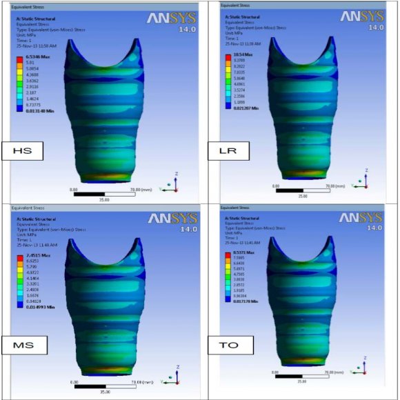
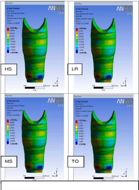
All the models and materials were compared on the basis of maximum equivalent von-mises stress which was noted after every analysis.
7. Conclusion
Static FEA was performed on a connecting rod by applying a compressive bearing load on its piston end making the crank end fixed. The design of existing connecting rod taken from reference paper [7] was modified and all the designs were tested with 2 different orthotropic materials.
From analysis it was inferred that a) Modifying the design parameters can yield better results. Since modified model I gave best results. Therefore this design proved to be the best among others tested.
b) Among 2 orthotropic materials investigated and compared the E-glass/epoxy proved to be best.

![Figure1: Model from reference paper[7]](https://engineeringresearch.org/index.php/GJRE/article/download/1040/version/100496/6-Design-Optimization-and-Comparative-Stress_html/10699/image-3.png)
| von-mises stresses in Mpa are | ||||
| S. | Compressiv | Existing | Our | Variation |
| no. | e Loads | Model | Model | (%) |
| 1. | 4319N | 71.20 | 74.816 | 4.83 |
| Maximum equivalent von-mises stress | ||
| Parameters | Eglass/ | Kevlar49/ |
| Epoxy (Mpa) | Epoxy (Mpa) | |
| Existing Model | 96.135 | 155.31 |
| Modified Model I | 80.995 | 121.95 |
| Variation*(%) | 15.75 | 21.479 |
| Modified Model 2 | 84.567 | 127.03 |
| Variation*(%) | 12.033 | 18.20 |
| Modified Model3 | 87.05 | 125.31 |
| Variation*(%) | 9.45 | 19.31 |