Effect of Seismic Load on Column Forces in RC Structures by Response Spectrum Analysis

Table of contents

1. I. Introduction a) Structural Systems

n the earliest structures at the beginning of the 20th century, structural members were assumed to carry primarily the gravity loads. Today, however, by the advances in structural design/systems and highstrength materials, building height is increased, which necessitates taking into consideration mainly the lateral loads such as wind and earthquake. Understandably, especially for the tall buildings, as the slenderness, and so the flexibility increases, buildings suffer from the lateral loads resulting from wind and earthquake more and more. As a general rule, when other things being equal, the taller the building, the more necessary it is to identify the proper structural system for resisting the lateral loads. Currently, there are many structural systems that can be used for the lateral resistance of tall buildings [2,3].

Structural systems of tall buildings can be divided into two broad categories: interior structures and exterior structures.

This classification is based on the distribution of the components of the primary lateral load-resisting system over the building.

2. b) Shear Wall Structure

Shear Wall-Frame Systems (Dual Systems), The system consists of reinforced concrete frames interacting with reinforced concrete shear walls are adequate for resisting both the vertical and the horizontal loads acting on them.

3. c) Necessity of Shear Walls

Shear wall system has two distinct advantages over a frame system.

? It provides adequate strength to resist large lateral loads with-out excessive additional cost.

? It provides adequate stiffness to resist lateral displacements to permissible limits, thus reducing risk of non-structural damage.

4. d) Seismic Load

The seismic weight of building is the sum of seismic weight of all the floors [8]. The seismic weight of each floor is its full dead load plus appropriate amount of imposed load, the latter being that part of the imposed loads that may reasonably be expected to be attached to the structure at the time of earthquake shaking. Earthquake forces experienced by a building result from ground motions (accelerations) which are also fluctuating or dynamic in nature, in fact they reverse direction somewhat chaotically [2,3]. In theory and practice, the lateral force that a building experiences from an earthquake increases in direct proportion with the acceleration of ground motion at the building site and the mass of the building. As the ground accelerates back and forth during an earthquake it imparts backand-forth (cyclic) forces to a building through its foundation which is forced to move with the ground [1].

5. e) Geo-Technical Consideration

The seismic motion that reaches a structure on the surface of the earth is influenced by local soil conditions. The subsurface soil layers underlying the building foundation may amplify the response of the building to earthquake motions originating in the bedrock.

6. Bearing Capacity of Foundation Soil

Three soil types are considered here: I. Hard -Those soils, which have an allowable bearing capacity of more than 10t/m2. II. Medium -Those soils, which have an allowable bearing capacity less than or equal to 10t/m2.

III. Soft -Those soils, which are liable to large differential settlement or liquefaction during an earthquake.

The allowable bearing pressure shall be determined in accordance with IS: 1888-1982 load test (Revision 1992). a) To understand and evaluation building structures and aims to the effect of Seismic load on column Forces in Different Type of RC Shear Walls in Concrete Frame Structures under Different Type of Soil Condition with seismic loading. b) Modeling a G+29 story high building for five different cases [9][10][11]. c) Analyzing the building dynamic analysis using linear, i.e. Response Spectrum Analysis [1][2][3]. d) Analyzing the results and arriving at conclusions.

7. a) Dynamic Analysis

Dynamic analysis may be executed to get the design seismic force, and its spread in different levels through the height of the building, and also various lateral load resisting element [1-2-3,8].

8. b) Response Spectrum Method

This method is executed to design spectrum, where as it is specified with a code for specific-site design can be used for a project site for the purposes of dynamic of steel and reinforce concrete buildings, the values of damping for building may be taken as 2 and 5 percent of the critical, respectively. response spectrum method is typically implemented in linear elastic procedures and also very much easier to use. This also called as or mode superposition method or model method, It also made on the idea of the superposition of responses given by the building through various modes of vibrations, each vibration modes is recorded as with its own particular deformed shape, with its own modal damping and its own frequency [7,8].

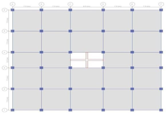
9. a) Details of the Building

A symmetrical building[15] of plan 38.5m X 35.5m located with location in high Seismic zone considered. Four bays of length 7.5m & one bays of length 8.5m along X -direction and four bays of length 7.5m & one bays of length 5.5m along Y -direction are provided. Shear is provided the center inner core of model building.

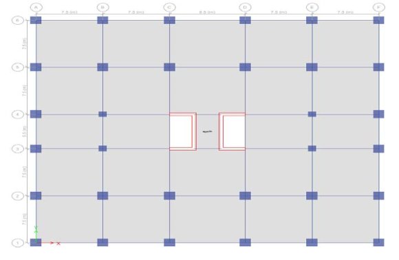
Struct I: G+29 story'stall building with Plus shape RC shear wall at the center of structure. Struct II: G+29 story'stall building with Box shape RC shear wall at the center of structure. Struct III: G+29 story'stall building with C-shape RC shear wall at the center of structure.

Struct IV: G+29 story'stall building with E-shape RC shear wall at the center of structure. Struct V: G+29 story'stall building with I-shape RC shear wall at the center of structure.

10. b) Load Combinations

As per IS 1893 (Part 1): 2002 Clause no. 6.3.1.2, the following load cases have to be considered for analysis: "1.2 (DL + IL ± EL)" "1.5 (DL ± EL)" "EQXP&EQYP" Earthquake load must be considered for +X, -X, +Y and -Y Directions [5][6][7]. EQXP & EQYP in different type of soil conditions (soft, medium and hard) were considered, in this regard we compared all column forces in different type of soil condition of structures II, III, IV, V with structure I (plus shape shear wall), also compared forces in hard and medium soils with soft soil for all five structures.

11. a) Discussion on Results

When a structure is subjected to earthquake, it responds by vibrating. An example force can be resolved into three mutually perpendicular directionstwo horizontal directions (X and Y directions) and the vertical direction (Z) [8]. This motion causes the structure to vibrate or shake in all three directions; the predominant direction of shaking is horizontal. All the structures are primarily designed for gravity loads-force equal to mass time's gravity in the vertical direction. Vertical acceleration should also be considered in structures with large spans those in which stability for design, or for overall stability analysis of structures. The basic intent of design theory for earthquake resistant structures is that buildings should be able to resist minor earthquakes without damage, resist moderate earthquakes without structural damage but with some non-structural damage. To avoid collapse during a major earthquake, Members must be ductile enough to absorb and dissipate energy by post elastic deformation. Redundancy in the structural system permits redistribution of internal forces in the event of the failure of key elements. When the primary element or system yields or fails, the lateral force can be redistributed to a secondary system to prevent progressive failure.

When a structure is subjected to an earthquake excitation, it interacts with the foundation and the soil, and thus changes the motion of the ground [2,8]. This means that the movement of the whole ground-structure system is influenced by the type of soil as well as by the type of structure. Understanding of soil structure interaction will enable the designer to design structures that will behave better during an earthquake.

From the above results and discussions, following conclusions can be drawn:

? The shear wall and it is position has a significant influenced on the time period, the time period is not influenced by the type of soil, in tall building with box shape Shear Walls is showing the low time period which shows a very significant performance. ? Shear is effected marginally by placing of the shear wall, grouping of shear wall and type of soil. The shear is increased by adding shear wall due to increase the seismic weight of the building. ? The Axial force and Moment in the column increases when the type of soil changes from hard to medium and medium to soft. Since the column moment increase as the soil type changes, soil structure interaction must be suitably considered while designing frames for seismic force. ? It is evident that the maximum column axial force is various with type of soil and placing of the shear wall. ? It is evident that the maximum column shear force in X-direction is influenced by the type of soil and placing of the shear wall. ? It is evident that the maximum column shear force in Y-direction has no influence on the type of soil and placing shear wall. ? It is evident that the maximum column torsion is same for all columns in a structure, but is influenced by the type of soil and placing shear wall. ? It is evident that the maximum column moment in Xdirection has no influence on the type of soil and placing shear wall. ? It is evident that the maximum column moment in Ydirection is influenced by the type of soil and placing of shear wall. ? It is evident that the results from1.2 (DL + IL ± EL) combination load is closed to the 1.5 (DL + EL) and there is no more difference between these combination load. ? Based on the analysis and discussion, shear wall are very much suitable for resisting earthquake induced lateral forces in multistoried structural systems when compared to multistoried structural systems whit out shear walls. They can be made to behave in a ductile manner by adopting proper detailing techniques. ? According to IS-1893:2002 the number of modes to be used in the analysis should be such that the total sum of modal masses of all modes considered is at least 90 percent of the total seismic mass. Here the maximum mass is for the tall building with box shape RC shear wall. ? ETABS is the robust software which is utilized foranalyzing any kind of multi building structures.

Figure 1. Figure 1 :Figure 2 :
12Figure 1: Plan of the Structure I
Figure 2. Figure 3 :Figure 4 :
34Figure 3: Plan of the Structure II
Figure 3. Figure 5 :Figure 6 :Figure 7 :
567Figure 5: Plan of the Structure III
Figure 4. Figure 8 :Figure 9 :Figure 10 :
8910Figure 8: 3D view showing shear wall location for Structure IV
Figure 5.
Figure 6.
Figure 7.
Figure 8. Table 1 :
1
Column Axial Force, P in Soft Soil Struct I Struct II Struct III Struct IV Struct V
Story "Column" "Unique -Name" "Load Case-Combo" "Station"m "P" "P" "P" "P" "P"
1ST C34 1.2(DL+LL+EQXP) 0 -24171.0618 -24285.0493 -24629.8602 -24381.5444 -24398.1773
1ST C34 1.2(DL+LL+EQXP) 1.45 -24103.093 -24217.0806 -24561.8915 -24313.5757 -24330.2086
1ST C34 1.2(DL+LL+EQXP) 2.9 -24035.1243 -24149.1118 -24493.9227 -24245.6069 -24262.2398
1ST C34 1.2(DL+LL+EQYP) 0 -23630.6382 -23276.1711 -23447.6424 -23345.1752 -23441.1649
1ST C34 1.2(DL+LL+EQYP) 1.45 -23562.6694 -23208.2023 -23379.6736 -23277.2065 -23373.1961
1ST C34 1.2(DL+LL+EQYP) 2.9 -23494.7007 -23140.2336 -23311.7049 -23209.2377 -23305.2274
Column Axial Force, P in Medium Soil
1ST C34 1.2(DL+LL+EQXP) 0 -24937.4993 -25121.0698 -25571.6279 -25446.3503 -25240.6514
1ST C34 1.2(DL+LL+EQXP) 1.45 -24869.5305 -25053.1011 -25503.6591 -25378.3816 -25172.6826
1ST C34 1.2(DL+LL+EQXP) 2.9 -24801.5618 -24985.1323 -25435.6904 -25310.4128 -25104.7139
1ST C34 1.2(DL+LL+EQYP) 0 -24202.5232 -23748.9954 -23963.8116 -23949.6572 -23939.1144
1ST C34 1.2(DL+LL+EQYP) 1.45 -24134.5545 -23681.0267 -23895.8428 -23881.6884 -23871.1456
1ST C34 1.2(DL+LL+EQYP) 2.9 -24066.5857 -23613.0579 -23827.8741 -23813.7197 -23803.1769
Column Axial Force, P in Hard Soil
1ST C34 1.2(DL+LL+EQXP) 0 -25597.4871 -25840.9764 -26382.5944 -26235.5482 -25966.1151
1ST C34 1.2(DL+LL+EQXP) 1.45 -25529.5184 -25773.0076 -26314.6257 -26167.5794 -25898.1464
1ST C34 1.2(DL+LL+EQXP) 2.9 -25461.5496 -25705.0389 -26246.6569 -26099.6107 -25830.1776
1ST C34 1.2(DL+LL+EQYP) 0 -24694.9798 -24156.1497 -24408.2906 -24397.697 -24367.9043
1ST C34 1.2(DL+LL+EQYP) 1.45 -24627.011 -24088.181 -24340.3219 -24329.7283 -24299.9355
1ST C34 1.2(DL+LL+EQYP) 2.9 -24559.0423 -24020.2122 -24272.3531 -24261.7595 -24231.9668
Figure 9. Table 2 :
2
Moment, M for structures with the load combination 1.2 (DL+LL+EQXP) &1.2 (DL+LL+EQYP), All
value in "kN-m"
Column Moment, M in Soft Soil Struct I Struct I Struct II Struct II Struct III Struct III Struct IV Struct IV Struct V Struct V
Sto ry Colu mn Load bo Case/Com Stati m on "M2" "M3" "M2" "M3" "M2" "M3" "M2" "M3" "M2" "M3"
1S T C34 1.2(DL+LL+ EQXP) 0 -244.01 18 979.47 15 -171.67 74 1061.1 112 -251.86 41 1421.2 435 -239.99 22 1271.7 973 -249.77 58 971.72 83
1S T C34 1.2(DL+LL+ EQXP) 1.45 -146.26 84 805.69 93 -84.416 8 912.71 96 -151.39 27 1219.8 181 -142.18 6 1095.4 925 -150.87 48 826.99 06
1S T C34 1.2(DL+LL+ EQXP) 2.9 -48.525 1 631.92 71 2.8438 764.32 8 -50.921 3 1018.3 927 -44.379 9 919.18 78 -51.973 8 682.25 29
1S T C34 1.2(DL+LL+ EQYP) 0 1727.5 733 -24.707 5 1026.4 07 -134.63 53 1218.6 199 -173.18 54 1153.6 344 -157.40 43 1174.9 664 -74.852 3
1S T C34 1.2(DL+LL+ EQYP) 1.45 1393.6 416 -70.519 4 893.97 23 -94.628 1027.4 053 -112.27 58 974.88 51 -107.00 72 954.74 75 -81.408 3
1S T C34 1.2(DL+LL+ EQYP) 2.9 1059.7 1 -116.33 13 761.53 75 -54.620 7 836.19 07 -51.366 3 796.13 58 -56.610 1 734.52 87 -87.964 4
Column Moment, M in Medium Soil
1S T C34 1.2(DL+LL+ EQXP) 0 -312.52 42 1329.5 266 -216.79 1461.8 423 -325.85 38 1958.0 803 -325.92 7 1862.7 469 -322.56 99 1328.7 543
1S T C34 1.2(DL+LL+ EQXP) 1.45 -197.67 08 1112.7 719 -115.99 39 1264.1 942 -207.08 2 1683.6 228 -206.75 27 1610.8 77 -205.97 96 1142.9 081
1S T C34 1.2(DL+LL+ EQXP) 2.9 -82.817 5 896.01 72 -15.197 8 1066.5 461 -88.310 2 1409.1 652 -87.578 5 1359.0 072 -89.389 3 957.06 19
1S T C34 1.2(DL+LL+ EQYP) 0 2368.8 316 -36.156 8 1412.6 049 -164.37 29 1674.0 045 -210.34 29 1686.2 828 -200.78 17 1615.0 795 -94.595 2
1S T C34 1.2(DL+LL+ EQYP) 1.45 1896.6 069 -78.885 5 1214.6 153 -105.79 85 1396.0 833 -128.02 5 1406.1 652 -125.34 18 1297.6 668 -92.514 4
1S T C34 1.2(DL+LL+ EQYP) 2.9 1424.3 822 -121.61 42 1016.6 256 -47.224 2 1118.1 621 -45.707 1126.0 477 -49.901 9 980.25 41 -90.433 6
Column Moment, M in Hard Soil
1S T C34 1.2(DL+LL+ EQXP) 0 -371.52 09 1630.9 629 -255.63 69 1806.9 164 -389.56 71 2420.3 565 -389.65 26 2300.9 465 -385.25 37 1636.1 935
1S T C34 1.2(DL+LL+ EQXP) 1.45 -241.93 4 1377.1 956 -143.18 53 1566.8 529 -255.03 67 2083.0 102 -254.63 2 1993.0 377 -253.43 1 1414.9 482
1S T C34 1.2(DL+LL+ EQXP) 2.9 -112.34 71 1123.4 282 -30.733 6 1326.7 894 -120.50 62 1745.6 638 -119.61 13 1685.1 289 -121.60 82 1193.7 03
1S T C34 1.2(DL+LL+ EQYP) 0 2921.0 262 -46.015 9 1745.1 642 -189.98 02 2066.1 412 -242.33 97 2081.2 226 -232.94 53 1994.0 659 -111.59 61
1S T C34 1.2(DL+LL+ EQYP) 1.45 2329.7 158 -86.089 7 1490.7 245 -115.41 76 1713.5 56 -141.58 67 1725.9 364 -138.93 69 1592.9 584 -102.07 8
1S T C34 1.2(DL+LL+ EQYP) 2.9 1738.4 055 -126.16 34 1236.2 848 -40.855 1360.9 708 -40.833 8 1370.6 502 -44.928 5
Figure 10. Table 3 :
3
Shear, V for structures with the load combination 1.2 (DL+LL+EQXP) & 1.2 (DL+LL+EQYP), All
value in "KN"
Column Shear, V in Soft Soil Struct I Struct I Struct II Struct II Struct III Struct III Struct IV Struct IV Struct V Struct V
Sto ry Colu mn Uniq ue Name Load Case/Comb o Stati on m "V2" "V3" "V2" "V3" "V2" "V3" "V2" "V3" "V2" "V3"
1ST C34 1.2(DL+LL+ EQXP) 0 119.8 429 -67.40 92 102.3 39 -60.17 98 138.9 141 -69.29 06 121.5 895 -67.45 25 99.81 91 -68.20 76
1ST C34 1.2(DL+LL+ EQXP) 1.45 119.8 429 -67.40 92 102.3 39 -60.17 98 138.9 141 -69.29 06 121.5 895 -67.45 25 99.81 91 -68.20 76
1ST C34 1.2(DL+LL+ EQXP) 2.9 119.8 429 -67.40 92 102.3 39 -60.17 98 138.9 141 -69.29 06 121.5 895 -67.45 25 99.81 91 -68.20 76
1ST C34 1.2(DL+LL+ EQYP) 0 31.59 44 230.2 977 -27.59 12 91.33 43 -42.00 66 131.8 722 -34.75 66 123.2 754 4.521 4 151.8 751
1ST C34 1.2(DL+LL+ EQYP) 1.45 31.59 44 230.2 977 -27.59 12 91.33 43 -42.00 66 131.8 722 -34.75 66 123.2 754 4.521 4 151.8 751
1ST C34 1.2(DL+LL+ EQYP) 2.9 31.59 44 230.2 977 -27.59 12 91.33 43 -42.00 66 131.8 722 -34.75 66 123.2 754 4.521 4 151.8 751
Column Shear, V in Medium Soil
1ST C34 1.2(DL+LL+ EQXP) 0 149.4 86 -79.20 92 136.3 091 -69.51 45 189.2 811 -81.91 16 173.7 034 -82.18 92 128.1 698 -80.40 71
1ST C34 1.2(DL+LL+ EQXP) 1.45 149.4 86 -79.20 92 136.3 091 -69.51 45 189.2 811 -81.91 16 173.7 034 -82.18 92 128.1 698 -80.40 71
1ST C34 1.2(DL+LL+ EQXP) 2.9 149.4 86 -79.20 92 136.3 091 -69.51 45 189.2 811 -81.91 16 173.7 034 -82.18 92 128.1 698 -80.40 71
1ST C34 1.2(DL+LL+ EQYP) 0 29.46 81 325.6 722 -40.39 61 136.5 446 -56.77 1 191.6 698 -52.02 75 193.1 845 -1.435 218.9 053
1ST C34 1.2(DL+LL+ EQYP) 1.45 29.46 81 325.6 722 -40.39 61 136.5 446 -56.77 1 191.6 698 -52.02 75 193.1 845 -1.435 218.9 053
1ST C34 1.2(DL+LL+ EQYP) 2.9 29.46 81 325.6 722 -40.39 61 136.5 446 -56.77 1 191.6 698 -52.02 75 193.1 845 -1.435 218.9 053
Column Shear, V in Hard Soil
1ST C34 1.2(DL+LL+ EQXP) 0 175.0 12 -89.37 03 165.5 61 -77.55 28 232.6 527 -92.77 96 212.3 509 -93.11 77 152.5 829 -90.91 22
1ST C34 1.2(DL+LL+ EQXP) 1.45 175.0 12 -89.37 03 165.5 61 -77.55 28 232.6 527 -92.77 96 212.3 509 -93.11 77 152.5 829 -90.91 22
1ST C34 1.2(DL+LL+ EQXP) 2.9 175.0 12 -89.37 03 165.5 61 -77.55 28 232.6 527 -92.77 96 212.3 509 -93.11 77 152.5 829 -90.91 22
1ST C34 1.2(DL+LL+ EQYP) 0 27.63 71 407.8 002 -51.42 25 175.4 757 -69.48 48 243.1 622 -64.83 34 245.0 25 -6.564 2 276.6 258
1ST C34 1.2(DL+LL+ EQYP) 1.45 27.63 71 407.8 002 -51.42 25 175.4 757 -69.48 48 243.1 622 -64.83 34 245.0 25 -6.564 2 276.6 258
1ST C34 1.2(DL+LL+ EQYP) 2.9 27.63 71 407.8 002 -51.42 25 175.4 757 -69.48 48 243.1 622 -64.83 34 245.0 25 -6.564 2 276.6 258
Note:

© 2023 Global Journ als Global Journal of Researches in Engineering ( ) E Volume Xx XIII Issue III V ersion I

Figure 11. Table 4 :
4
Column Torsion, T in Soft Soil Struct I Struct II Struct III Struct IV Struct V
Story "Column" "Unique-Name" "Load Case-Combo" "Station"m "T" "T" "T" "T" "T"
1ST C34 67 1.2(DL+LL+EQXP) 0 -41.6175 -29.3334 -44.901 -42.3525 -43.8436
1ST C34 67 1.2(DL+LL+EQXP) 1.45 -41.6175 -29.3334 -44.901 -42.3525 -43.8436
1ST C34 67 1.2(DL+LL+EQXP) 2.9 -41.6175 -29.3334 -44.901 -42.3525 -43.8436
1ST C34 67 1.2(DL+LL+EQYP) 0 45.3145 31.9525 48.8724 46.1375 48.5638
1ST C34 67 1.2(DL+LL+EQYP) 1.45 45.3145 31.9525 48.8724 46.1375 48.5638
1ST C34 67 1.2(DL+LL+EQYP) 2.9 45.3145 31.9525 48.8724 46.1375 48.5638
Column Torsion, T in Medium Soil
1ST C34 67 1.2(DL+LL+EQXP) 0 -56.5981 -39.8539 -61.0208 -61.1008 -59.584
1ST C34 67 1.2(DL+LL+EQXP) 1.45 -56.5981 -39.8539 -61.0208 -61.1008 -59.584
1ST C34 67 1.2(DL+LL+EQXP) 2.9 -56.5981 -39.8539 -61.0208 -61.1008 -59.584
1ST C34 67 1.2(DL+LL+EQYP) 0 61.6294 43.4949 66.5111 66.66 66.09
1ST C34 67 1.2(DL+LL+EQYP) 1.45 61.6294 43.4949 66.5111 66.66 66.09
1ST C34 67 1.2(DL+LL+EQYP) 2.9 61.6294 43.4949 66.5111 66.66 66.09
Column Torsion, T in Hard Soil
1ST C34 67 1.2(DL+LL+EQXP) 0 -69.4981 -48.9132 -74.9017 -75.004 -73.1383
1ST C34 67 1.2(DL+LL+EQXP) 1.45 -69.4981 -48.9132 -74.9017 -75.004 -73.1383
1ST C34 67 1.2(DL+LL+EQXP) 2.9 -69.4981 -48.9132 -74.9017 -75.004 -73.1383
1ST C34 67 1.2(DL+LL+EQYP) 0 75.6784 53.4342 81.6999 81.8788 81.182
1ST C34 67 1.2(DL+LL+EQYP) 1.45 75.6784 53.4342 81.6999 81.8788 81.182
1ST C34 67 1.2(DL+LL+EQYP) 2.9 75.6784 53.4342 81.6999 81.8788 81.182
Figure 12. Table 5 :
5
Year 2023
10
Global Journal of Researches in Engineering "Story" 1ST 1ST 1ST 1ST 1ST 1ST 1ST 1ST 1ST 1ST Column Axial Force, Pin Soft Soil "Column" "Unique-Name" "Load Case-Combo" C34 1.5(DL+EQXP) C34 1.5(DL+EQXP) C34 1.5(DL+EQXP) C34 1.5(DL+EQYP) C34 1.5(DL+EQYP) C34 1.5(DL+EQYP) C34 1.5(DL+EQXP) C34 1.5(DL+EQXP) C34 1.5(DL+EQXP) C34 1.5(DL+EQYP) Struct I "P" -25183.8699 -25098.9089 -25013.948 -24508.3404 -24423.3794 -24338.4185 Column Axial Force, P in Medium Soil Struct II "Station"m "P" 0 -25355.396 1.45 -25270.435 2.9 -25185.4741 0 -24094.2982 1.45 -24009.3372 2.9 -23924.3763 0 -26141.9168 -26400.4216 1.45 -26056.9558 -26315.4607 2.9 -25971.9949 -26230.4998 0 -25223.1967 -24685.3286 Struct III "P" -25767.3656 -25682.4047 -25597.4437 -24289.5933 -24204.6324 -24119.6714 -26944.5752 -26859.6142 -26774.6533 -24934.8048 Struct IV "P" -25468.0736 -25383.1127 -25298.1518 -24172.6121 -24087.6512 -24002.6903 -26799.081 -26714.1201 -26629.1591 -24928.2146 Struct V "P" -25450.8356 -25365.8747 -25280.9137 -24254.57 -24169.6091 -24084.6481 -26503.9282 -26418.9672 -26334.0063 -24877.0069
1ST C34 1.5(DL+EQYP) 1.45 -25138.2357 -24600.3677 -24849.8439 -24843.2537 -24792.046
1ST C34 1.5(DL+EQYP) 2.9 -25053.2748 -24515.4068 -24764.8829 -24758.2927 -24707.0851
Column Axial Force, P in Hard Soil
1ST C34 1.5(DL+EQXP) 0 -26966.9016 -27300.3048 -27958.2834 -27785.5783 -27410.7578
1ST C34 1.5(DL+EQXP) 1.45 -26881.9407 -27215.3439 -27873.3224 -27700.6174 -27325.7969
1ST C34 1.5(DL+EQXP) 2.9 -26796.9797 -27130.383 -27788.3615 -27615.6564 -27240.836
1ST C34 1.5(DL+EQYP) 0 -25838.7674 -25194.2715 -25490.4036 -25488.2644 -25412.9943
1ST C34 1.5(DL+EQYP) 1.45 -25753.8064 -25109.3106 -25405.4426 -25403.3035 -25328.0334
1ST C34 1.5(DL+EQYP) 2.9 -25668.8455 -25024.3496 -25320.4817 -25318.3425 -25243.0724
Note:

Axial Force, P for structures with the load combination 1.5 (DL+EQXP) & 1.5 (DL+EQYP), All value in "kN" © 2023 Global Journ als ( ) E Volume Xx XIII Issue III V ersion I

Figure 13. Table 6 :
6
Column Moment, M in Soft Soil Struct I Struct I Struct II Struct II Struct III Struct III Struct IV Struct IV Struct V Struct V
"Story" "Column" "Unique -Name" "Load Combo" Case- "Station"m "M2" "M3" "M2" "M3" "M2" "M3" "M2" "M3" "M2" "M3"
1ST C34 1.5(DL+ EQXP) 0 -300.97 13 1225.7 47 -213.58 1343.4 34 -313.8 242 1800.2 079 -298.97 71 1609.5 397 -311.21 44 1219.4 677
1ST C34 1.5(DL+ EQXP) 1.45 -185.76 63 1027.6 976 -111.24 83 1165.8 496 -194.9 693 1551.5 389 -183.46 03 1395.0 708 -194.32 03 1051.1 982
1ST C34 1.5(DL+ EQXP) 2.9 -70.561 4 829.64 82 -8.9167 988.26 53 -76.11 45 1302.8 699 -67.943 6 1180.6 019 -77.426 3 882.92 88
1ST 1ST C34 C34 1.5(DL+ EQYP) 1.5(DL+ EQYP) 0 1.45 2163.5 101 1739.1 213 -29.476 6 -67.575 7 1284.0 256 1111.7 38 -151.24 91 -93.334 9 1524. 2808 1278. 5282 -192.82 82 -113.57 85 1443.0 562 1212.8 786 -176.96 23 -108.05 39 1469.7 135 1187.7 076 -88.758 4 -84.300 Year 2023
1ST 1ST 1ST 1ST 1ST 1ST 1ST 1ST 1ST 1ST 1ST 1ST 1ST C34 C34 C34 C34 C34 C34 C34 C34 C34 C34 C34 C34 C34 1.5(DL+ EQYP) 1.5(DL+ EQXP) 1.5(DL+ EQXP) 1.5(DL+ EQXP) 1.5(DL+ EQYP) 1.5(DL+ EQYP) 1.5(DL+ EQYP) 1.5(DL+ EQXP) 1.5(DL+ EQXP) 1.5(DL+ EQXP) 1.5(DL+ EQYP) 1.5(DL+ EQYP) 1.5(DL+ EQYP) 2.9 0 1.45 2.9 0 1.45 2.9 0 1.45 2.9 0 1.45 2.9 1314.7 324 Column Moment, M in Medium Soil -105.67 48 939.45 04 -35.420 6 -386.6 118 1663.3 159 -269.97 07 1844. 3479 -250.0 193 1411.5 384 -150.71 97 1605. 1929 -113.4 269 1159.7 609 -31.468 7 1366. 0378 2965. 0829 -43.788 3 1766.7 729 -188.4 211 2367. 8278 -78.033 4 1512.5 417 -107.2 981 1770. 5727 -112.27 85 1258.3 105 -26.17 5 Column Moment, M in Hard Soil -460.3 577 2040.1 114 -318.52 93 2275. 6905 -305.3 483 1742.0 68 -184.70 89 1983. 5162 -150.3 389 1444.0 245 -50.888 5 1691. 342 3655. 3261 -56.112 2 2182.4 72 -220.4 303 2909. 214 -87.038 6 1857.6 783 -119.3 219 2163. 1019 -117.96 5 1532.8 845 -18.21 35 1032. 7756 -406.31 13 -264.58 1 -122.85 06 2093.5 115 1739.3 757 1385.2 398 -485.95 3 -324.52 43 -163.09 56 2583.6 823 2136.2 165 1688.7 508 -34.328 8 2471.2 54 2131.2 948 1791.3 356 -239.27 51 -133.26 49 -27.254 7 3049.0 992 2630.5 29 2211.9 588 -279.27 11 -150.21 71 -21.163 2 982.70 11 -406.39 56 -264.16 87 -121.94 18 2108.8 666 1751.9 788 1395.0 909 -486.05 26 -324.01 77 -161.98 28 2602.5 414 2151.6 928 1700.8 441 -39.145 4 2348.2 268 2039.3 015 1730.3 762 -231.18 4 -2 -30.760 1 2895.9 762 2517.0 023 2138.0 283 -271.38 85 -147.96 59 -24.543 4 130.97 905.70 -402.20 7 -263.20 13 -124.19 57 2019.8 549 567 586 -480.56 17 -322.51 55 -164.46 93 2493.5 878 1985.4 712 1477.3 547 1212.8 1616.3 18 9 1665.7 503 1446.0 951 1226.4 4 -113.43 67 98.183 82.929 4 2050.0 492 1786.1 453 1522.2 413 -134.68 77 -110.13 75 -85.587 3 ---79.842 Global Journal of Researches in Engineering E ( ) Volume Xx XIII Issue III V ersion I 11
© 2023 Global Journ als
Figure 14. Table 7 :
7
Column Shear, V in Soft Soil Struct I Struct I Struct II Struct II Struct III Struct III Struct IV Struct IV Struct V Struct V
"Story" "Colum n" "Unique -Name" "Load Combo" Case- "Station "m "V2" "V3" "V2" "V3" "V2" "V3" "V2" "V3" "V2" "V3"
1ST C34 67 1.5(DL+ EQXP) 0 136.58 58 -79.45 17 122.47 2 -70.573 6 171.49 59 -81.968 9 147.90 96 -79.666 7 116.04 79 -80.61 66
1ST C34 67 1.5(DL+ EQXP) 1.45 136.58 58 -79.45 17 122.47 2 -70.573 6 171.49 59 -81.968 9 147.90 96 -79.666 7 116.04 79 -80.61 66
1ST C34 67 1.5(DL+ EQXP) 2.9 136.58 58 -79.45 17 122.47 2 -70.573 6 171.49 59 -81.968 9 147.90 96 -79.666 7 116.04 79 -80.61 66
Year 2023 1ST 1ST C34 C34 67 67 1.5(DL+ EQYP) 1.5(DL+ EQYP) 0 1.45 26.275 2 26.275 2 292.6 819 292.6 819 -39.940 9 -39.940 9 118.81 9 118.81 9 -54.654 9 -54.654 9 169.48 46 169.48 46 -47.523 1 -47.523 1 158.74 31 158.74 31 -3.0742 -3.0742 194.4 868 194.4 868
Global Journal of Researches in Engineering E ( ) Volume Xx XIII Issue III V ersion I 12 1ST 1ST 1ST 1ST 1ST 1ST 1ST 1ST 1ST 1ST 1ST 1ST 1ST C34 C34 C34 C34 C34 C34 C34 C34 C34 C34 C34 C34 C34 67 67 67 67 67 67 67 67 67 67 67 67 67 1.5(DL+ EQYP) 1.5(DL+ EQXP) 1.5(DL+ EQXP) 1.5(DL+ EQXP) 1.5(DL+ EQYP) 1.5(DL+ EQYP) 1.5(DL+ EQYP) 1.5(DL+ EQXP) 1.5(DL+ EQXP) 1.5(DL+ EQXP) 1.5(DL+ EQYP) 1.5(DL+ EQYP) 1.5(DL+ EQYP) 2.9 0 1.45 2.9 0 1.45 2.9 0 1.45 2.9 0 1.45 2.9 26.275 2 Column Shear, V in Medium Soil 292.6 819 -39.940 9 118.81 9 173.63 97 -94.201 7 164.93 45 -82.242 1 173.63 97 -94.201 7 164.93 45 -82.242 1 173.63 97 -94.201 7 164.93 45 -82.242 1 23.617 3 411.90 01 -55.946 9 175.33 19 23.617 3 411.90 01 -55.946 9 175.33 19 23.617 3 411.90 01 -55.946 9 175.33 19 Column Shear, V in Hard Soil 205.54 72 -106.90 31 201.49 95 -92.289 9 205.54 72 -106.90 31 201.49 95 -92.289 9 205.54 72 -106.90 31 201.49 95 -92.289 9 21.328 5 514.56 01 -69.729 9 223.99 57 21.328 5 514.56 01 -69.729 9 223.99 57 21.328 5 514.56 01 -69.729 9 223.99 57 -54.654 9 234.45 46 234.45 46 234.45 46 -73.110 5 -73.110 5 -73.110 5 288.66 91 288.66 91 288.66 91 -89.002 7 -89.002 7 -89.002 7 169.48 46 -97.745 1 -97.745 1 -97.745 1 244.23 16 244.23 16 244.23 16 -111.33 02 -111.33 02 -111.33 02 308.59 71 308.59 71 308.59 71 -1 213.05 19 213.05 19 213.05 19 -69.111 7 -69.111 7 -69.111 7 261.36 13 261.36 13 261.36 13 -85.119 -85.119 -85.119 47.523 31 -98.087 5 -98.087 5 -98.087 5 246.12 96 246.12 96 246.12 96 -111.74 82 -111.74 82 -111.74 82 310.93 01 310.93 01 310.93 01 158.74 3.0742 151.48 63 151.48 63 151.48 63 -10.519 7 -7 -10.519 7 182.00 27 182.00 27 182.00 27 -16.931 2 -16.931 2 -16.931 2 10.519 - -95.86 6 -95.86 6 -95.86 6 278.2 746 746 746 -108.9 974 -108.9 974 -108.9 974 350.4 252 350.4 252 350.4 252 278.2 278.2 868 194.4
© 2023 Global Journ als
Figure 15. Table 8 :
8
Column Torsion, T in Soft Soil Struct I Struct II Struct III Struct IV Struct V
"Story" "Column" "Unique-Name" "Load Case-Combo" "Station"m "T" "T" "T" "T" "T"
1ST C34 67 1.5(DL+EQXP) 0 -52.0172 -36.6355 -56.0881 -52.909 -54.7871
1ST C34 67 1.5(DL+EQXP) 1.45 -52.0172 -36.6355 -56.0881 -52.909 -54.7871
1ST C34 67 1.5(DL+EQXP) 2.9 -52.0172 -36.6355 -56.0881 -52.909 -54.7871
1ST C34 67 1.5(DL+EQYP) 0 56.6478 39.9718 61.1286 57.7035 60.7221
1ST C34 67 1.5(DL+EQYP) 1.45 56.6478 39.9718 61.1286 57.7035 60.7221
1ST C34 67 1.5(DL+EQYP) 2.9 56.6478 39.9718 61.1286 57.7035 60.7221
Column Torsion, T in Medium Soil
1ST C34 67 1.5(DL+EQXP) 0 -70.743 -49.7861 -76.2378 -76.3444 -74.4626
1ST C34 67 1.5(DL+EQXP) 1.45 -70.743 -49.7861 -76.2378 -76.3444 -74.4626
1ST C34 67 1.5(DL+EQXP) 2.9 -70.743 -49.7861 -76.2378 -76.3444 -74.4626
1ST C34 67 1.5(DL+EQYP) 0 77.0414 54.3999 83.1769 83.3566 82.6299
1ST C34 67 1.5(DL+EQYP) 1.45 77.0414 54.3999 83.1769 83.3566 82.6299
1ST C34 67 1.5(DL+EQYP) 2.9 77.0414 54.3999 83.1769 83.3566 82.6299
Column Torsion, T in Hard Soil
1ST C34 67 1.5(DL+EQXP) 0 -86.8679 -61.1102 -93.589 -93.7234 -91.4055
1ST C34 67 1.5(DL+EQXP) 1.45 -86.8679 -61.1102 -93.589 -93.7234 -91.4055
1ST C34 67 1.5(DL+EQXP) 2.9 -86.8679 -61.1102 -93.589 -93.7234 -91.4055
1ST C34 67 1.5(DL+EQYP) 0 94.6026 66.824 102.1629 102.3801 101.4949
1ST C34 67 1.5(DL+EQYP) 1.45 94.6026 66.824 102.1629 102.3801 101.4949
1ST C34 67 1.5(DL+EQYP) 2.9 94.6026 66.824 102.1629 102.3801 101.4949
Figure 16. Table 9 :
9
Year 2023
13
Volume Xx XIII Issue III V ersion I
( ) E
"Story" 1ST 1ST 1ST 1ST 1ST 1ST 1ST 1ST 1ST 1ST 1ST Column Axial Force, P in Soft Soil "Column" "Unique-Name" "Load Case-Combo" C34 EQXP C34 EQXP C34 EQXP C34 EQYP C34 EQYP C34 EQYP C34 EQXP C34 EQXP C34 EQXP C34 EQYP C34 EQYP Struct I "P" -1774.1609 -1774.1609 -1774.1609 -1323.8079 -1323.8079 -1323.8079 Column Axial Force, P in Medium Soil Struct II "Station"m "P" 0 -1935.2327 1.45 -1935.2327 2.9 -1935.2327 0 -1094.5008 1.45 -1094.5008 2.9 -1094.5008 0 -2412.8589 -2631.9165 1.45 -2412.8589 -2631.9165 2.9 -2412.8589 -2631.9165 0 -1800.3788 -1488.5211 1.45 -1800.3788 -1488.5211 Struct III "P" -2180.0176 -2180.0176 -2180.0176 -1194.8361 -1194.8361 -1194.8361 -2964.824 -2964.824 -2964.824 -1624.9771 -1624.9771 Struct IV "P" -1997.9011 -1997.9011 -1997.9011 -1134.2601 -1134.2601 -1134.2601 -2885.2394 -2885.2394 -2885.2394 -1637.9951 -1637.9951 Struct V "P" -1950.1714 -1950.1714 -1950.1714 -1152.661 -1152.661 -1152.661 -2652.2331 -2652.2331 -2652.2331 -1567.6189 -1567.6189 Global Journal of Researches in Engineering
1ST C34 EQYP 2.9 -1800.3788 -1488.5211 -1624.9771 -1637.9951 -1567.6189
Column Axial Force, P in Hard Soil
1ST C34 EQXP 0 -2962.8488 -3231.8386 -3640.6295 -3542.9042 -3256.7862
1ST C34 EQXP 1.45 -2962.8488 -3231.8386 -3640.6295 -3542.9042 -3256.7862
1ST C34 EQXP 2.9 -2962.8488 -3231.8386 -3640.6295 -3542.9042 -3256.7862
1ST C34 EQYP 0 -2210.7593 -1827.8164 -1995.3763 -2011.3616 -1924.9438
1ST C34 EQYP 1.45 -2210.7593 -1827.8164 -1995.3763 -2011.3616 -1924.9438
1ST C34 EQYP 2.9 -2210.7593 -1827.8164 -1995.3763 -2011.3616 -1924.9438
© 2023 Global Journ als
Figure 17. Table 10 :
10
Column Moment, M in Soft Soil Struct I Struct I Struct II Struct II Struct III Struct III Struct IV Struct IV Struct V Struc t V
"Stor y" "Column" "Unique-Name" "Load Case-Combo" "Station"m "M2" "M3" "M2" "M3" "M2" "M3" "M2" "M3" "M2" "M3"
1ST C34 EQXP 0 -158.5935 810.312 8 -104.427 2 927.618 4 -171.27 25 1242.67 79 -161.363 1109. 5618 -168.5 048 826.4 492
1ST C34 EQXP 1.45 -118.987 710.816 2 -73.0951 813.598 6 -128.91 04 1073.62 19 -121.236 7 967.6 594 -127.5 574 731.2 906
1ST C34 EQXP 2.9 -79.3805 611.319 7 -41.763 699.578 8 -86.548 4 904.566 -81.1104 825.7 569 -86.60 99 636.1 319
Year 2023 1ST 1ST C34 C34 EQYP EQYP 0 1.45 1484.394 1 1164.271 4 -26.503 -19.366 893.976 6 742.229 1 -68.837 -25.8578 1054.1 309 853.42 12 -86.0128 -36.4563 999.992 5 809.655 9 -81.43 95 -34.42 38 1018. 7804 793.7 946 -45.70 12 -25.70 85
Global Journal of Researches in Engineering E ( ) Volume Xx XIII Issue III V ersion I 14 1ST 1ST 1ST 1ST 1ST 1ST 1ST 1ST 1ST 1ST 1ST 1ST 1ST C34 C34 C34 C34 C34 C34 C34 C34 C34 C34 C34 C34 C34 EQYP EQXP EQXP EQXP EQYP EQYP EQYP EQXP EQXP EQXP EQYP EQYP EQYP 2.9 0 1.45 2.9 0 1.45 2.9 0 1.45 2.9 0 1.45 2.9 844.1487 -215.6871 -161.8223 -107.9575 2018.776 1583.409 1 1148.042 2 -264.8511 -198.7083 -132.5655 2478.938 1 1944.333 2 1409.728 3 -12.229 Column Moment, M in Medium Soil 590.481 7 17.1215 1102.02 54 -142.020 9 1261.56 1 966.710 1 -99.4093 1106.49 41 831.394 8 -56.7977 951.427 1 -36.0441 1215.80 81 -93.6183 -26.3378 1009.43 16 -35.1666 -16.6314 803.055 1 23.2852 Column Moment, M in Hard Soil 1353.22 23 -174.393 4 1549.12 27 1187.06 31 -122.068 8 1358.70 96 1020.90 39 -69.7443 1168.29 65 -44.26 1492.94 09 -114.957 8 -32.3412 1239.52 26 -43.1825 -20.4224 986.104 4 28.5929 652.71 16 -232.93 06 -175.31 82 -117.70 58 1433.6 18 1160.6 529 887.68 78 -286.02 51 -215.28 04 -144.53 58 1760.3 985 1425.2 135 1090.0 284 13.1002 1690.04 19 1460.12 58 1230.20 98 -116.977 5 -49.5806 17.8162 2075.27 21 1792.94 86 1510.62 52 -143.641 4 -60.8821 21.8773 619.319 3 -232.975 4 -175.042 3 -117.109 3 1443.86 61 1169.05 6 894.245 9 -286.08 -214.941 7 -143.803 3 1772.98 27 1435.53 2 1098.08 13 12.59 2 1602.0 199 1397.1 465 1192.2 73 -117.58 73 -49.702 5 2 1967.1 862 1715.6 137 1464.0 411 -144.39 03 -61.031 8 22.326 7 18.182 568.8 -229.16 66 -173.47 8 -117.78 95 1385.5 413 1079.5 773.58 -281.40 31 -213.02 08 -144.63 86 1701.3 633 1325.6 37 949.91 07 607 088 1123 .971 994. 5552 865. 1394 -62.1 537 636 35 1380 .170 2 1221 .255 3 1062 .340 3 -76.3 21 -42.9 332 -9.54 54 7.77 --34.9 8 -5.715
© 2023 Global Journ als
Figure 18. Table 11 :
11
Column Shear, V in Soft Soil Struct I Struct I Struct II Struct II Struct III Struct III Struct IV Struct IV Struct V Struct V
"Story" "Unique -Name" "V2" "V3" "V2" "V3" "V2" "V3" "V2" "V3" "V2" "V3"
1ST C34 67 EQXP 0 68.6183 -27.3148 78.6344 -21.6083 116.590 3 -29.2152 97.8638 -27.6733 65.62 67 -28.2396
1ST C34 67 EQXP 1.45 68.6183 -27.3148 78.6344 -21.6083 116.590 3 -29.2152 97.8638 -27.6733 65.62 67 -28.2396
1ST C34 67 EQXP 2.9 68.6183 -27.3148 78.6344 -21.6083 116.590 3 -29.2152 97.8638 -27.6733 65.62 67 -28.2396
1ST C34 67 EQYP 0 -4.9221 220.774 3 -29.6409 104.653 4 -34.1769 138.420 4 -32.4246 131.2666 -13.78 81 155.162 6
1ST C34 67 EQYP 1.45 -4.9221 220.774 3 -29.6409 104.653 4 -34.1769 138.420 4 -32.4246 131.2666 -13.78 81 155.162 6
1ST C34 67 EQYP 2.9 -4.9221 220.774 3 -29.6409 104.653 4 -34.1769 138.420 4 -32.4246 131.2666 -13.78 81 155.162 6
Column Shear, V in Medium Soil
1ST C34 67 EQXP 0 93.3209 -37.1481 106.942 7 -29.3873 158.562 8 -39.7327 141.292 -39.9538 89.2523 -38.4059
1ST C34 67 EQXP 1.45 93.3209 -37.1481 106.942 7 -29.3873 158.562 8 -39.7327 141.292 -39.9538 89.2523 -38.4059
1ST C34 67 EQXP 2.9 93.3209 -37.1481 106.942 7 -29.3873 158.562 8 -39.7327 141.292 -39.9538 89.2523 -38.4059
1ST C34 67 EQYP 0 -6.694 300.253 -40.3116 142.328 6 -46.4806 188.251 8 -46.8171 189.524 2 -18.7518 211.021 2
1ST C34 67 EQYP 1.45 -6.694 300.253 -40.3116 142.328 6 -46.4806 188.251 8 -46.8171 189.524 2 -18.7518 211.021 2
1ST C34 67 EQYP 2.9 -6.694 300.253 -40.3116 142.328 6 -46.4806 188.251 8 -46.8171 189.524 2 -18.7518 211.021 2
Column Shear, V in Hard Soil
1ST C34 67 EQXP 0 114.592 6 -45.6157 131.319 4 -36.0859 194.705 8 -48.7894 173.498 3 -49.0609 109.596 5 -47.1602
1ST C34 67 EQXP 1.45 114.592 6 -45.6157 131.319 4 -36.0859 194.705 8 -48.7894 173.498 3 -49.0609 109.596 5 -47.1602
1ST C34 67 EQXP 2.9 114.592 6 -45.6157 131.319 4 -36.0859 194.705 8 -48.7894 173.498 3 -49.0609 109.596 5 -47.1602
1ST C34 67 EQYP 0 -8.2199 368.693 -49.5002 174.771 2 -57.0754 231.162 1 -57.4886 232.724 6 -23.0261 259.121 6
1ST C34 67 EQYP 1.45 -8.2199 368.693 -49.5002 174.771 2 -57.0754 231.162 1 -57.4886 232.724 6 -23.0261 259.121 6
1ST C34 67 EQYP 2.9 -8.2199 368.693 -49.5002 174.771 2 -57.0754 231.162 1 -57.4886 232.724 6 -23.0261 259.121 6
Figure 19. Table 12 :
12
"Load
"Column" Case- "Station"m
Combo"
Year 2023
15
Volume Xx XIII Issue III V ersion I
( ) E
"Story" 1ST 1ST 1ST 1ST 1ST 1ST 1ST 1ST "Column" C34 C34 C34 C34 C34 C34 C34 C34 Column Torsion, T in Soft Soil "Unique-Name" "Load Case-Combo" EQXP EQXP EQXP EQYP EQYP EQYP EQXP EQXP Struct I "T" -34.6774 -34.6774 -34.6774 37.766 37.766 37.766 Column Torsion, T in Medium Soil Struct II "Station"m "T" 0 -24.353 1.45 -24.353 2.9 -24.353 0 26.7186 1.45 26.7186 2.9 26.7186 0 -47.1612 -33.12 1.45 -47.1612 -33.12 Struct III "T" -37.3143 -37.3143 -37.3143 40.8301 40.8301 40.8301 -50.7475 -50.7475 Struct IV "T" -35.2051 -35.2051 -35.2051 38.5365 38.5365 38.5365 -50.8287 -50.8287 Struct V "T" -36.4362 -36.4362 -36.4362 40.5699 40.5699 40.5699 -49.5533 -49.5533 Global Journal of Researches in Engineering
1ST C34 EQXP 2.9 -47.1612 -33.12 -50.7475 -50.8287 -49.5533
1ST C34 EQYP 0 51.3617 36.3373 55.529 55.6386 55.1751
1ST C34 EQYP 1.45 51.3617 36.3373 55.529 55.6386 55.1751
1ST C34 EQYP 2.9 51.3617 36.3373 55.529 55.6386 55.1751
Column Torsion, T in Hard Soil
1ST C34 EQXP 0 -57.9112 -40.6695 -62.315 -62.4147 -60.8485
1ST C34 EQXP 1.45 -57.9112 -40.6695 -62.315 -62.4147 -60.8485
1ST C34 EQXP 2.9 -57.9112 -40.6695 -62.315 -62.4147 -60.8485
© 2023 Global Journ als
Figure 20. Table 13 :
13
Modal Load Participation Ratios Struct I Struct I Struct II Struct II Struct III Struct III Struct IV Struct IV Struct V Struct V
"Case" "Item Type" "Item" "Static" "Dynamic" "Static" "Dynamic "Static" "Dynamic" "Static" "Dynamic" "Static" "Dynamic"
% % % % % % % % % %
Modal Acceleration UX 99.82 86.71 99.99 94.7 99.98 94.59 99.99 94.54 99.97 91.54
Modal Acceleration UY 99.79 87.46 99.98 91.46 99.97 91.85 99.97 91.83 99.97 92.51
Modal Acceleration UZ 0 0 0 0 0 0 0 0 0 0
Note:

Graph 1: Modal Load Participation Ratios of Structures

Figure 21. Table 14 :
14
Year 2023
16
Volume Xx XIII Issue III V ersion I
( ) E
Global Journal of Researches in Engineering Case Modal Modal Modal Modal Modal Modal Modal Modal Modal Mode 1 2 3 4 5 6 7 8 9 Struct I Period sec 6.298 6.248 5.545 2.062 1.952 1.603 1.191 1.027 0.803 Frequency cyc/sec 0.159 0.16 0.18 0.485 0.512 0.624 0.84 0.974 1.245 Period sec 5.785 5.606 4.684 1.701 1.547 1.475 0.9 0.838 0.645 Struct II Frequency cyc/sec 0.173 0.178 0.213 0.588 0.646 0.678 1.112 1.193 1.551 Period sec 6.415 6.32 5.767 2.114 1.958 1.568 1.219 1.028 0.82 Struct III Frequency cyc/sec 0.156 0.158 0.173 0.473 0.511 0.638 0.82 0.972 1.22 Period sec 6.375 6.21 5.792 2.102 1.901 1.575 1.212 0.983 0.815 Struct IV Frequency cyc/sec 0.157 0.161 0.173 0.476 0.526 0.635 0.825 1.017 1.226 Period sec 6.382 5.694 5.642 2.088 1.565 1.524 1.19 0.791 0.711 Struct V Frequency cyc/sec 0.157 0.176 0.177 0.479 0.639 0.656 0.84 1.264 1.406
Modal 10 0.782 1.279 0.613 1.632 0.711 1.406 0.714 1.401 0.703 1.423
Modal 11 0.645 1.55 0.5 2.002 0.641 1.56 0.604 1.656 0.565 1.769
Modal 12 0.581 1.72 0.45 2.222 0.592 1.689 0.589 1.697 0.423 2.363
© 2023 Global Journ als
Figure 22. Table 15 :
15
Column axial forces "P" Struct II Struct III Struct IV Struct V
"Story" "Column" "Unique -Name" "Load Case-Combo" "Station"m "P" "P" "P" "P"
1ST C34 67 1.2(DL+LL+EQXP) 0,1.45,2.9 0% 2% 1% 1%
1ST C34 67 1.2(DL+LL+EQYP) 0,1.45,2.9 -2% -1% -1% -1%
1ST C34 67 1.5(DL+EQXP) 0,1.45,2.9 1% 2% 1% 1%
1ST C34 67 1.5(DL+EQYP) 0,1.45,2.9 -2% -1% -1% -1%
1ST C34 67 EQXP 0,1.45,2.9 8% 19% 11% 9%
1ST C34 67 EQYP 0,1.45,2.9 -21% -11% -17% -15%
Figure 23. Table 16 :
16
Column axial forces "P" Struct II Struct III Struct IV Struct V
"Story" "Column" "Unique-Name" "Load Case-Combo" "Station"m "P" "P" "P" "P"
1ST C34 67 1.2(DL+LL+EQXP) 0,1.45,2.9 1% 2% 2% 1%
1ST C34 67 1.2(DL+LL+EQYP) 0,1.45,2.9 -2% -1% -1% -1%
1ST C34 67 1.5(DL+EQXP) 0,1.45,2.9 1% 3% 2% 1%
1ST C34 67 1.5(DL+EQYP) 0,1.45,2.9 -2% -1% -1% -1%
1ST C34 67 EQXP 0,1.45,2.9 8% 19% 16% 9%
1ST C34 67 EQYP 0,1.45,2.9 -21% -11% -10% -15%
Figure 24. Table 17 :
17
Column axial forces "P" Struct II Struct III Struct IV Struct V
"Story" "Column" "Unique -Name" "Load Case-Combo" "Station"m "P" "P" "P" "P"
1ST C34 67 1.2(DL+LL+EQXP) 0,1.45,2.9 1% 3% 2% 1%
1ST C34 67 1.2(DL+LL+EQYP) 0,1.45,2.9 -2% -1% -1% -1%
1ST C34 67 1.5(DL+EQXP) 0,1.45,2.9 1% 4% 3% 2%
1ST C34 67 1.5(DL+EQYP) 0,1.45,2.9 -3% -1% -1% -2%
1ST C34 67 EQXP 0,1.45,2.9 8% 19% 16% 9%
1ST C34 67 EQYP 0,1.45,2.9 -21% -11% -10% -15%
Figure 25. Table 18 :
18
Column moment forces "M" Struct II Struct III Struct IV Struct V
"Story" "Column" "Unique -Name" "Load Case-Combo" "Station"m "M" "M" "M" "M"
1ST C34 67 1.2(DL+LL+EQXP) 0,1.45,2.9 564% 4% -5% 4%
1ST C34 67 1.2(DL+LL+EQYP) 0,1.45,2.9 -54% -35% -42% -46%
1ST C34 67 1.5(DL+EQXP) 0,1.45,2.9 -54% 4% -1% 4%
1ST C34 67 1.5(DL+EQYP) 0,1.45,2.9 -62% -39% -47% -47%
1ST C34 67 EQXP 0,1.45,2.9 0% 45% 41% 44%
1ST C34 67 EQYP 0,1.45,2.9 0% 13% 8% 5%
Figure 26. Table 19 :
19
Column moment forces "M" Struct II Struct III Struct IV Struct V
"Story" "Column" "Unique -Name" "Load Case-Combo" "Station"m "M" "M" "M" "M"
1ST C34 67 1.2(DL+LL+EQXP) 0,1.45,2.9 -187% 5% 5% 5%
1ST C34 67 1.2(DL+LL+EQYP) 0,1.45,2.9 -55% -35% -34% -46%
1ST C34 67 1.5(DL+EQXP) 0,1.45,2.9 -55% 5% 5% 4%
1ST C34 67 1.5(DL+EQYP) 0,1.45,2.9 -62% -39% -38% -47%
1ST C34 67 EQXP 0,1.45,2.9 0% 45% 45% 44%
1ST C34 67 EQYP 0,1.45,2.9 0% 13% 13% 5%
Figure 27. Table 20 :
20
Column moment forces "M" Struct II Struct III Struct IV Struct V
"Story" "Column" "Unique -Name" "Load Case-Combo" "Station"m "M" "M" "M" "M"
1ST C34 67 1.2(DL+LL+EQXP) 0,1.45,2.9 -127% 6% 5% 5%
1ST C34 67 1.2(DL+LL+EQYP) 0,1.45,2.9 -55% -35% -34% -46%
1ST C34 67 1.5(DL+EQXP) 0,1.45,2.9 -55% 6% 6% 5%
1ST C34 67 1.5(DL+EQYP) 0,1.45,2.9 -62% -39% -38% -47%
1ST C34 67 EQXP 0,1.45,2.9 0% 45% 45% 44%
1ST C34 67 EQYP 0,1.45,2.9 0% 13% 13% 5%
Figure 28. Table 21 :
21
Column shear forces "V" Struct II Struct III Struct IV Struct V
"Story" "Column" "Unique -Name" "Load Case-Combo" "Station"m "V" "V" "V" "V"
1ST C34 67 1.2(DL+LL+EQXP) 0,1.45,2.9 -17% 14% 1% -20%
1ST C34 67 1.2(DL+LL+EQYP) 0,1.45,2.9 215% 175% 191% -599%
1ST C34 67 1.5(DL+EQXP) 0,1.45,2.9 -12% 20% 8% -18%
1ST C34 67 1.5(DL+EQYP) 0,1.45,2.9 166% 148% 155% 955%
1ST C34 67 EQXP 0,1.45,2.9 13% 41% 30% -5%
1ST C34 67 EQYP 0,1.45,2.9 83% 86% 85% 64%
Figure 29. Table 22 :
22
Column shear forces "V" Struct II Struct III Struct IV Struct V
"Story" "Column" "Unique -Name" "Load Case-Combo" "Station"m "V" "V" "V" "V"
1ST C34 67 1.2(DL+LL+EQXP) 0,1.45,2.9 -10% 21% 14% -17%
1ST C34 67 1.2(DL+LL+EQYP) 0,1.45,2.9 173% 152% 157% 2154%
1ST C34 67 1.5(DL+EQXP) 0,1.45,2.9 -5% 26% 18% -15%
1ST C34 67 1.5(DL+EQYP) 0,1.45,2.9 142% 132% 134% 325%
1ST C34 67 EQXP 0,1.45,2.9 13% 41% 34% -5%
1ST C34 67 EQYP 0,1.45,2.9 83% 86% 86% 64%
Figure 30. Table 23 :
23
Column shear forces "V" Struct II Struct III Struct IV Struct V
"Story" "Column" "Unique -Name" "Load Case-Combo" "Station"m "V" "V" "V" "V"
1ST C34 67 1.2(DL+LL+EQXP) 0,1.45,2.9 -6% 25% 18% -15%
1ST C34 67 1.2(DL+LL+EQYP) 0,1.45,2.9 154% 140% 143% 521%
1ST C34 67 1.5(DL+EQXP) 0,1.45,2.9 -2% 29% 21% -13%
1ST C34 67 1.5(DL+EQYP) 0,1.45,2.9 131% 124% 125% 226%
1ST C34 67 EQXP 0,1.45,2.9 13% 41% 34% -5%
1ST C34 67 EQYP 0,1.45,2.9 83% 86% 86% 64%
Figure 31. Table 24 :
24
Column torsion forces "T" Struct II Struct III Struct IV Struct V
"Story" "Column" "Unique-Name" "Load Case-Combo" "Station"m "T" "T" "T" "T"
1ST C34 67 1.2(DL+LL+EQXP) 0,1.45,2.9 -42% 7% 2% 5%
1ST C34 67 1.2(DL+LL+EQYP) 0,1.45,2.9 -42% 7% 2% 7%
1ST C34 67 1.5(DL+EQXP) 0,1.45,2.9 -42% 7% 2% 5%
1ST C34 67 1.5(DL+EQYP) 0,1.45,2.9 -42% 7% 2% 7%
1ST C34 67 EQXP 0,1.45,2.9 -42% 7% 1% 5%
1ST C34 67 EQYP 0,1.45,2.9 -41% 8% 2% 7%
Figure 32. Table 25 :
25
Column torsion forces "T" Struct II Struct III Struct IV Struct V
"Story" "Column" "Unique -Name" "Load Case-Combo" "Station"m "T" "T" "T" "T"
1ST C34 67 1.2(DL+LL+EQXP) 0,1.45,2.9 -42% 7% 7% 5%
1ST C34 67 1.2(DL+LL+EQYP) 0,1.45,2.9 -42% 7% 8% 7%
1ST C34 67 1.5(DL+EQXP) 0,1.45,2.9 -42% 7% 7% 5%
1ST C34 67 1.5(DL+EQYP) 0,1.45,2.9 -42% 7% 8% 7%
1ST C34 67 EQXP 0,1.45,2.9 -42% 7% 7% 5%
1ST C34 67 EQYP 0,1.45,2.9 -41% 8% 8% 7%
Column torsion forces "T" Struct II Struct III Struct IV Struct V
"Story" "Unique -Name" "Load Case-Combo" "Station"m "T" "T" "T" "T"
1ST C34 67 1.2(DL+LL+EQXP) 0,1.45,2.9 -42% 7% 7% 5%
1ST C34 67 1.2(DL+LL+EQYP) 0,1.45,2.9 -42% 7% 8% 7%
1ST C34 67 1.5(DL+EQXP) 0,1.45,2.9 -42% 7% 7% 5%
1ST C34 67 1.5(DL+EQYP) 0,1.45,2.9 -42% 7% 8% 7%
1ST C34 67 EQXP 0,1.45,2.9 -42% 7% 7% 5%
1ST C34 67 EQYP 0,1.45,2.9 -41% 8% 8% 7%
Figure 33. Table 27 :
27
"Column"
Column Axial Forces "P" "Medium soil" "Hard soil"
"Story" "Column" "Unique-Name" "Load Case-Combo" "Station"m "P" "P"
1ST C34 67 1.2(DL+LL+EQXP) 0,1.45,2.9 3% 6%
1ST C34 67 1.2(DL+LL+EQYP) 0,1.45,2.9 2% 4%
1ST C34 67 1.5(DL+EQXP) 0,1.45,2.9 4% 7%
1ST C34 67 1.5(DL+EQYP) 0,1.45,2.9 3% 5%
1ST C34 67 EQXP 0,1.45,2.9 26% 40%
1ST C34 67 EQYP 0,1.45,2.9 26% 40%
Figure 34. Table 26 :
26
Year 2023
21
Volume Xx XIII Issue III V ersion I
( ) E
Global Journal of Researches in Engineering
© 2023 Global Journ als
Figure 35. Table 28 :
28
Column Axial Forces "P" "Medium soil" "Hard soil"
"Story" "Column" "Unique-Name" "Load Case-Combo" "Station"m "P" "P"
1ST C34 67 1.2(DL+LL+EQXP) 0,1.45,2.9 3% 6%
1ST C34 67 1.2(DL+LL+EQYP) 0,1.45,2.9 2% 4%
1ST C34 67 1.5(DL+EQXP) 0,1.45,2.9 4% 7%
1ST C34 67 1.5(DL+EQYP) 0,1.45,2.9 2% 4%
1ST C34 67 EQXP 0,1.45,2.9 26% 40%
1ST C34 67 EQYP 0,1.45,2.9 26% 40%
Figure 36. Table 29 :
29
Column Axial Forces "P" "Medium soil" "Hard soil"
"Story" "Column" "Unique-Name" "Load Case-Combo" "Station"m "P" "P"
1ST C34 67 1.2(DL+LL+EQXP) 0,1.45,2.9 4% 7%
1ST C34 67 1.2(DL+LL+EQYP) 0,1.45,2.9 2% 4%
1ST C34 67 1.5(DL+EQXP) 0,1.45,2.9 4% 8%
1ST C34 67 1.5(DL+EQYP) 0,1.45,2.9 3% 5%
1ST C34 67 EQXP 0,1.45,2.9 26% 40%
1ST C34 67 EQYP 0,1.45,2.9 26% 40%
Figure 37. Table 30 :
30
Column Axial Forces "P" "Medium soil" "Hard soil"
"Story" "Column" "Unique-Name" "Load Case-Combo" "Station"m "P" "P"
1ST C34 67 1.2(DL+LL+EQXP) 0,1.45,2.9 4% 7%
1ST C34 67 1.2(DL+LL+EQYP) 0,1.45,2.9 3% 4%
1ST C34 67 1.5(DL+EQXP) 0,1.45,2.9 5% 8%
1ST C34 67 1.5(DL+EQYP) 0,1.45,2.9 3% 5%
1ST C34 67 EQXP 0,1.45,2.9 31% 44%
1ST C34 67 EQYP 0,1.45,2.9 31% 44%
Figure 38. Table 31 :
31
Column Axial Forces "P" "Medium soil" "Hard soil"
"Story" "Column" "Unique-Name" "Load Case-Combo" "Station"m "P" "P"
1ST C34 67 1.2(DL+LL+EQXP) 0,1.45,2.9 3% 6%
1ST C34 67 1.2(DL+LL+EQYP) 0,1.45,2.9 2% 4%
1ST C34 67 1.5(DL+EQXP) 0,1.45,2.9 4% 7%
1ST C34 67 1.5(DL+EQYP) 0,1.45,2.9 3% 5%
1ST C34 67 EQXP 0,1.45,2.9 26% 40%
1ST C34 67 EQYP 0,1.45,2.9 26% 40%
Figure 39. Table 32 :
32
Column Moment Forces "M" "Medium soil" "Hard soil"
"Story" "Column" "Unique-Name" "Load Case-Combo" "Station"m "M" "M"
1ST C34 67 1.2(DL+LL+EQXP) 0,1.45,2.9 20% 32%
1ST C34 67 1.2(DL+LL+EQYP) 0,1.45,2.9 -7% -14%
1ST C34 67 1.5(DL+EQXP) 0,1.45,2.9 21% 34%
1ST C34 67 1.5(DL+EQYP) 0,1.45,2.9 -11% -23%
1ST C34 67 EQXP 0,1.45,2.9 26% 40%
1ST C34 67 EQYP 0,1.45,2.9 26% 40%
Figure 40. Table 33 :
33
Column Moment Forces "M" "Medium soil" "Hard soil"
"Story" "Column" "Unique-Name" "Load Case-Combo" "Station"m "M" "M"
1ST C34 67 1.2(DL+LL+EQXP) 0,1.45,2.9 25% 38%
1ST C34 67 1.2(DL+LL+EQYP) 0,1.45,2.9 32% 46%
1ST C34 67 1.5(DL+EQXP) 0,1.45,2.9 26% 39%
1ST C34 67 1.5(DL+EQYP) 0,1.45,2.9 29% 43%
1ST C34 67 EQXP 0,1.45,2.9 26% 40%
1ST C34 67 EQYP 0,1.45,2.9 26% 40%
Figure 41. Table 34 :
34
Column Moment Forces "M" "Medium soil" "Hard soil"
"Story" "Column" "Unique-Name" "Load Case-Combo" "Station"m "M" "M"
1ST C34 67 1.2(DL+LL+EQXP) 0,1.45,2.9 27% 40%
1ST C34 67 1.2(DL+LL+EQYP) 0,1.45,2.9 26% 40%
1ST C34 67 1.5(DL+EQXP) 0,1.45,2.9 27% 41%
1ST C34 67 1.5(DL+EQYP) 0,1.45,2.9 25% 39%
1ST C34 67 EQXP 0,1.45,2.9 26% 40%
1ST C34 67 EQYP 0,1.45,2.9 26% 40%
Figure 42. Table 35 :
35
Column Moment Forces "M" "Medium soil" "Hard soil"
"Story" "Column" "Unique-Name" "Load Case-Combo" "Station"m "M" "M"
1ST C34 67 1.2(DL+LL+EQXP) 0,1.45,2.9 30% 43%
1ST C34 67 1.2(DL+LL+EQYP) 0,1.45,2.9 33% 46%
1ST C34 67 1.5(DL+EQXP) 0,1.45,2.9 31% 43%
1ST C34 67 1.5(DL+EQYP) 0,1.45,2.9 31% 44%
1ST C34 67 EQXP 0,1.45,2.9 31% 44%
1ST C34 67 EQYP 0,1.45,2.9 31% 44%
Figure 43. Table 36 :
36
Column Moment Forces "M" "Medium soil" "Hard soil"
"Story" "Column" "Unique-Name" "Load Case-Combo" "Station"m "M" "M"
1ST C34 67 1.2(DL+LL+EQXP) 0,1.45,2.9 22% 35%
1ST C34 67 1.2(DL+LL+EQYP) 0,1.45,2.9 415% 169%
1ST C34 67 1.5(DL+EQXP) 0,1.45,2.9 23% 36%
1ST C34 67 1.5(DL+EQYP) 0,1.45,2.9 71% 82%
1ST C34 67 EQXP 0,1.45,2.9 26% 40%
1ST C34 67 EQYP 0,1.45,2.9 26% 40%
Figure 44. Table 37 :
37
Column Shear Forces "V" "Medium soil" "Hard soil"
"Story" "Column" "Unique-Name" "Load Case-Combo" "Station"m "V" "V"
1ST C34 67 1.2(DL+LL+EQXP) 0,1.45,2.9 30% 44%
1ST C34 67 1.2(DL+LL+EQYP) 0,1.45,2.9 26% 40%
1ST C34 67 1.5(DL+EQXP) 0,1.45,2.9 29% 42%
1ST C34 67 1.5(DL+EQYP) 0,1.45,2.9 26% 40%
1ST C34 67 EQXP 0,1.45,2.9 26% 40%
1ST C34 67 EQYP 0,1.45,2.9 26% 40%
Figure 45. Table 38 :
38
Column Shear Forces "V" "Medium soil" "Hard soil"
"Story" "Column" "Unique-Name" "Load Case-Combo" "Station"m "V" "V"
1ST C34 67 1.2(DL+LL+EQXP) 0,1.45,2.9 56% 61%
1ST C34 67 1.2(DL+LL+EQYP) 0,1.45,2.9 26% 40%
1ST C34 67 1.5(DL+EQXP) 0,1.45,2.9 40% 52%
1ST C34 67 1.5(DL+EQYP) 0,1.45,2.9 26% 40%
1ST C34 67 EQXP 0,1.45,2.9 26% 40%
1ST C34 67 EQYP 0,1.45,2.9 26% 40%
Figure 46. Table 39 :
39
Column Shear Forces "V" "Medium soil" "Hard soil"
"Story" "Column" "Unique-Name" "Load Case-Combo" "Station"m "V" "V"
1ST C34 67 1.2(DL+LL+EQXP) 0,1.45,2.9 31% 45%
1ST C34 67 1.2(DL+LL+EQYP) 0,1.45,2.9 26% 40%
1ST C34 67 1.5(DL+EQXP) 0,1.45,2.9 29% 43%
1ST C34 67 1.5(DL+EQYP) 0,1.45,2.9 26% 40%
1ST C34 67 EQXP 0,1.45,2.9 26% 40%
1ST C34 67 EQYP 0,1.45,2.9 26% 40%
Figure 47. Table 40 :
40
Column Shear Forces "V" "Medium soil" "Hard soil"
"Story" "Column" "Unique-Name" "Load Case-Combo" "Station"m "V" "V"
1ST C34 67 1.2(DL+LL+EQXP) 0,1.45,2.9 36% 48%
1ST C34 67 1.2(DL+LL+EQYP) 0,1.45,2.9 31% 43%
1ST C34 67 1.5(DL+EQXP) 0,1.45,2.9 34% 47%
1ST C34 67 1.5(DL+EQYP) 0,1.45,2.9 31% 43%
1ST C34 67 EQXP 0,1.45,2.9 31% 44%
1ST C34 67 EQYP 0,1.45,2.9 31% 44%
Figure 48. Table 41 :
41
Column Shear Forces "V" "Medium soil" "Hard soil"
"Story" "Column" "Unique-Name" "Load Case-Combo" "Station"m "V" "V"
1ST C34 67 1.2(DL+LL+EQXP) 0,1.45,2.9 30% 44%
1ST C34 67 1.2(DL+LL+EQYP) 0,1.45,2.9 26% 40%
1ST C34 67 1.5(DL+EQXP) 0,1.45,2.9 29% 43%
1ST C34 67 1.5(DL+EQYP) 0,1.45,2.9 26% 40%
1ST C34 67 EQXP 0,1.45,2.9 26% 40%
1ST C34 67 EQYP 0,1.45,2.9 26% 40%
Figure 49. Table 42 :
42
Column Torsion Forces "T" "Medium soil" "Hard soil"
"Story" "Column" "Unique-Name" "Load Case-Combo" "Station"m "T" "T"
1ST C34 67 1.2(DL+LL+EQXP) 0,1.45,2.9 0% 0%
1ST C34 67 1.2(DL+LL+EQYP) 0,1.45,2.9 26% 40%
1ST C34 67 1.5(DL+EQXP) 0,1.45,2.9 26% 40%
1ST C34 67 1.5(DL+EQYP) 0,1.45,2.9 26% 40%
1ST C34 67 EQXP 0,1.45,2.9 26% 40%
1ST C34 67 EQYP 0,1.45,2.9 26% 40%
Figure 50. Table 43 :
43
Column Torsion Forces "T" "Medium soil" "Hard soil"
"Story" "Column" "Unique-Name" "Load Case-Combo" "Station"m "T" "T"
1ST C34 67 1.2(DL+LL+EQXP) 0,1.45,2.9 26% 40%
1ST C34 67 1.2(DL+LL+EQYP) 0,1.45,2.9 27% 40%
1ST C34 67 1.5(DL+EQXP) 0,1.45,2.9 26% 40%
1ST C34 67 1.5(DL+EQYP) 0,1.45,2.9 27% 40%
1ST C34 67 EQXP 0,1.45,2.9 26% 40%
1ST C34 67 EQYP 0,1.45,2.9 26% 40%
Figure 51. Table 44 :
44
Column Torsion Forces "T" "Medium soil" "Hard soil"
"Story" "Column" "Unique-Name" "Load Case-Combo" "Station"m "T" "T"
1ST C34 67 1.2(DL+LL+EQXP) 0,1.45,2.9 26% 40%
1ST C34 67 1.2(DL+LL+EQYP) 0,1.45,2.9 27% 40%
1ST C34 67 1.5(DL+EQXP) 0,1.45,2.9 26% 40%
1ST C34 67 1.5(DL+EQYP) 0,1.45,2.9 27% 40%
1ST C34 67 EQXP 0,1.45,2.9 26% 40%
1ST C34 67 EQYP 0,1.45,2.9 26% 40%
Figure 52. Table 45 :
45
Column Torsion Forces "T" "Medium soil" "Hard soil"
"Story" "Column" "Unique-Name" "Load Case-Combo" "Station"m "T" "T"
1ST C34 67 1.2(DL+LL+EQXP) 0,1.45,2.9 31% 44%
1ST C34 67 1.2(DL+LL+EQYP) 0,1.45,2.9 31% 44%
1ST C34 67 1.5(DL+EQXP) 0,1.45,2.9 31% 44%
1ST C34 67 1.5(DL+EQYP) 0,1.45,2.9 31% 44%
1ST C34 67 EQXP 0,1.45,2.9 31% 44%
1ST C34 67 EQYP 0,1.45,2.9 31% 44%
Figure 53. Table 46 :
46
Column Torsion Forces "T" "Medium soil" "Hard soil"
"Story" "Column" "Unique-Name" "Load Case-Combo" "Station"m "T" "T"
1ST C34 67 1.2(DL+LL+EQXP) 0,1.45,2.9 26% 40%
1ST C34 67 1.2(DL+LL+EQYP) 0,1.45,2.9 27% 40%
1ST C34 67 1.5(DL+EQXP) 0,1.45,2.9 26% 40%
1ST C34 67 1.5(DL+EQYP) 0,1.45,2.9 27% 40%
1ST C34 67 EQXP 0,1.45,2.9 26% 40%
1ST C34 67 EQYP 0,1.45,2.9 26% 40%

Appendix A

Appendix A.1 Acknowledgments

The author would like to express his gratitude to all the individuals for their expertise throughout all aspects of our study and contribution to writing the manuscript. The author would like to express his gratitude to the Nanjing Forestry University, China, for funding this research work through the project No. 163050206 & foreign young talents project No. QN2021014006L. In addition, I thank the anonymous reviewers for their fruitful suggestions to improve the article. The author is truly grateful to all of you. Year 2023 14. Gaikwad Ujwala Vithal, "Effect of Shear Wall on Seismic Behavior of Unsymmetrical Reinforced Concrete Structure", International Journal of Research and Scientific Innovation (IJRSI) Volume IV, Issue X, October 2017. 15. Mahantesh S Patil & R B Khadiranaikar, "Dynamic Analysis of High Rise RC Structure with Shear Walls and Coupled Shear Walls", International Journal of Advance Engineering and Research Development, Volume 2, Issue 8, August, 2015. 16. Durgesh C. Rai, Sudhir K. Jain and C. V. R. Murty, "Seismic Design of RC Structures", short course, conducted by Department of Civil Engineering, IIT Kanpur, Ahmedabad, India, Nov 25-30, 2012.

Appendix B

Appendix B.1 Data Availability Statement

All data generated or analysed during this study are included in this article.

Appendix C

Appendix C.1 Conflict of Interest

The author declare no conflict of interest.

Appendix D

  1. Live loads on buildings and Structures, (New Delhi, India
    ) 1987. 875.
  2. Berkeley . ETABS Integrated Building Design Software, (California, USA
    ) February 2003.
  3. Criteria for earthquake resistant design of structures General provisions and buildings. IS 1893 (part 1), (New Delhi, India
    ) 2002.
  4. Dead loads on buildings and Structures. IS 1987. New Delhi, India. 875 (1) .
  5. Ductile detailing of reinforced concrete structures subjected to seismic forces-Code of Practice, 1993. New Delhi, India.. 13920.
  6. Dynamics of Structures: Theory and Application to Earthquake Engineering, 2012. New Delhi. (4th edition)
  7. Earthquake Resistant Design of Structures, (New Delhi
    ) 2010. Oxford University Press.
  8. Design of concrete shear wall buildings for earthquake induced torsion. J L Humar , S Yavari . Canada June, 2002. (14 structural conference of the Canadian society for civil engineering)
  9. How to Model and Design High Rise Building Using ETABS Program, Makar Nageh . 2007. Cairo.
  10. Seismic behaviour of RCC shear wall under different soil conditions, N Anand , C Mightraj , G Prince Arulraj . december 2010. p. . (Indian geotechnical conference)
  11. Plain and Reinforced Concrete-Code of practice. IS 2000. New Delhi, India. 456.
  12. Structural Dynamics: Theory & computations, (New Delhi
    ) 2004. CBS Publishers & Distributors. (Second Edition)
  13. Seismic Design of Reinforced Concrete and Masonry Buildings, T Paulay , M J Priestley . 1992. New York: INC.
Date: 1970-01-01