1. Introduction
ncremental sheet metal forming is a new method, which consists of improved possibilities of sheet metal forming. Now days, incremental sheet metal forming has become very attractive method for making 3-D complex shapes. The main advantage of this process is the cost and time reduction by eliminating the making of special purpose dies. With the controlled movement of a tool; wide range of 3D shapes can be formed directly from the CAD model by moving the tool along an optimized path. This process is suitable for small batch production as well as to fabricate complex geometries [1][2][3][4].
There are several ways in which various ISF methods can be categorized. The traditional method is to define through the surface shape achieved with the process, i.e. convex surface or the concave surface. [5][6]. Incremental CNC forming technology can be used to achieve non-symmetrical shapes formed on the concave surface [7]. The convex surface forming was the first variation of ISF, known as Die less NC Forming. It was introduced in Japan by Matsubara [8].
The current ISF processes can be divided in various groups, depending on the number of contact points between sheet and tool and also on the clamping mechanism. The first is the 'Single Point Incremental Sheet Forming' (SPISF), where only a single tool is used to form the component. The sheet is supported only at the edges with the clamps. Other variant is the 'Two point Incremental Sheet forming' (TPISF), where a full or partial stationary die is present to support the sheet.
The advanced variants are under research where the support die is also moving [9]. Another interesting variant under research is the ISF by hammering [10][11]. Most of the ISF configurations use the 3 axis CNC machines as the base, but new configurations based on the robotized tools are also experimented [12][13]. Kitazawa has implemented ISF using a lathe [14][15]. In order to achieve the desired accuracy in the form and dimension using ISF, it is important to know the factors influencing the process and their relationship. Several attempts have been made to investigate the behavior of the sheet metal in ISF [16][17][18][19].
In literature, many experiments on die less forming have been reported, but the effect of tool geometry on sheet metal deformation process is not well defined. Most of the experiments performed to obtain a range of wall angles in the case of sheet metal deformation use either a hemispherical or ball nose tool. In the present work, specific experiments have been carried out to achieve a range of wall angles varying from wall angle 50? to 75? with a step size of 5?, so that comparative study between three different tool geometries can be performed.
2. II.
3. Experimental Details a) Process description and tooling setup
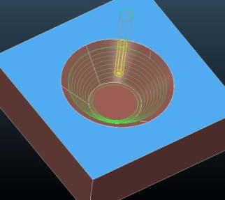
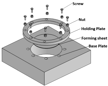
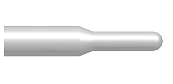
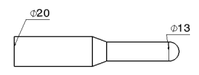
The usual forming strategy in ISF consists of a single forming stage where the tool traces along a sequence of contour lines with a small vertical down motion in between (Fig. 1). In general for forming of sheet, a hemispherical or ball nose tool is used but to observe the effect of contact area on formability, this tool is compared with two other tools, for the same process parameters. The experiments have been carried out with sheet metal specimen supported about its contour and rigidly fixed with the fixture with the help of normal clamping device [Fig. 3]. There is no lateral movement of the sheet during forming. This whole arrangement was fixed on to the worktable of the milling machine. At any instant only a small portion of the sheet is subjected to the local deformation. In the present work, tools made up of stainless steel are clamped in the spindle of the milling machine. The experiments are performed on aluminum sheets of 1 mm thickness with single point incremental sheet forming. From the experimental observations and available literatures most influencing parameters for single point incremental sheet metal forming are listed below (Table 1). During the experiment, process parameters have been kept same; apart from wall angle and tool diameter (Fig. 5), for all the three tool geometries to obtain the comparative study.
4. c) The force measurements
The knowledge about the deformation force is very important for successful forming operation and to achieve final geometry precisely. It also helps in the selection of appropriate equipment.
In order to identify deformation force and to avoid tool failure the experiments have been carried out.
The force measurement set-up is shown in Fig. 6. It consists of SPISF fixture, which is mounted on the piezoelectric dynamometer. The dynamometer is also connected with the data acquisition board and a PC for output signals. The output signals have been recorded at 1000 Hz frequency for accurate results. Experiments have been carried out for wall angles of 50 ? to 75?, with step size of 5? and as represented in Fig. 7, which shows the effect of wall angle on maximum forming force (Fz). With other process parameters same as in Table 1, cone geometry is formed up to 80 mm depth and actual data is plotted. To maintain the accuracy data (Force measurement) has been recorded at high frequency (1000 Hz).
5. Fig. 7: Comparison of maximum forces for various wall angles
By increasing the wall angle the magnitude of maximum force occur during forming continuously increase. In case of lower wall angles (below 65 ?) the force distribution is uniform but when wall angle exceeds 70? the force tends to increase continuously. In case of 70? wall angle, the desired depth is achieved, but in case of 75? wall angle, the fracture occurs at a depth of 14 mm only. Thus, the value of maximum force for 75 ? wall angle can be used to define the limit in case of SPIF for 1 mm thick aluminum sheet.
6. e) Effect of tool diameter
To see the effect of tool diameter on forming forces, experiments have been carried out for the wall angle of 50? and tool diameter of 7 mm, 10 mm and 13 mm respectively, with other process parameters remaining same (Table 1).
With increase in the tool diameter the value of maximum forming forces also increase (Fig. 8); this happens because the contact area between tool and sheet increases with the increase in tool diameter.
Similar results are obtained for remaining wall angles as well.
7. Fig. 8: Comparison of forces for different tool diameter
In case of steeper wall angle (above 70 ? in our case) the forming limit of specimen decreases as shown in Fig. 9. For the 7 mm tool the sheet can be formed up to 14 mm depth, whereas in case of 10 and 13 mm diameter tool forming limit is 12 and 10 mm respectively. Fig. 9: Forming limit for different tool diameters
8. f) Comparison of different tool geometries
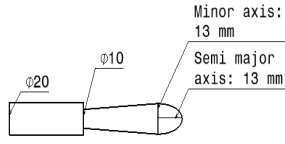
A set of experiments have been performed and it is observed that the maximum deformation force in case of elliptical tool tip is considerably low as compared to spherical tool tip (Fig. 10-12). The reason behind is that, in case of elliptical tool the contact area between tool and sheet is considerably low as compared to spherical one. Due to the absence of overloading the forming limit of the specimen has increased. In case of steeper wall angles (above 70 ?) the forming limit of the component with the elliptical tool increases considerably. For 1 mm aluminum sheet forming limit in case of spherical tool is 14 mm but in case of elliptical tool with straight wall it is 19 mm and for elliptical tool with tapered wall it is 21 mm (Fig. 13). Fig. 13: Forming limit for different tool geometries in case of tool diameter 13 mm and wall angle 75?
When the tool is at certain depth in case of steeper wall angles there arises a problem of collision between the tool and the wall of the sheet specimen. To overcome this problem, authors have suggested tool with tapered wall. By the graph (Fig. 13) it can be noticed that forming limit increases considerably in case of tool with tapered wall.
In the present work, contact area is calculated for both the tools in case of 50 ? wall angle and 0.5 mm step down (Fig. 14) for same forming depth. It is found that in case of spherical tool contact area is larger than the elliptical tool.
9. Simulation Results
The single point incremental sheet forming process has been simulated in finite element analysis software, LS-DYNA. Anisotropic yield criteria, material model Hill, Bar lat and multi-linear stress-strain approaches have been employed [20]. For the tool, Solid -164 tetrahedral mesh element, and rigid body behavior and for the sheet shell-163 square element, plastic anisotropic body behavior is employed. The values of the yield stress, density, young's modulus and Poisson's ratio have been set for high carbon steel (Tool) and aluminum (sheet).
Simulations have been carried out for spherical and elliptical tools of diameter 7 mm, 10 mm and 13 mm and wall angle of 50 ? to 75? with a step size 5?. This work presents a case where tool diameter is of 13 mm and wall angle 50 ?. Same tool path as given to the CNC-milling machine is defined through array parameters in the LS-DYNA and value of maximum deformation force is identified.
Simulation results are shown with the help of Fig. 16 IV.
10. Conclusions
A study to observe the effect of tool geometry on the formability of the component for conical shape is performed for different tool diameters and wall angles. It is found that by changing the tool geometry from spherical to elliptical shape the forming limit of specimen increases considerably. Through the analysis, it is observed that contact area plays major role in terms of deformation force, which directly affects the forming limit of the component. In addition the elliptical tool with tapered wall gives more forming limit. Further when the tool deals with steeper wall angles the problem of tool collision with the wall of specimen has been solved.
The ISF process is simulated in FEM LS-DYNA and by comparing experimental and simulation results, a good correlation of forces is observed.

![Fig.14: Tool sheet interface at 50? wall angleAs we can see that, contact area in case of spherical tool [Fig.15 (a)] is 0.03569 m2 but in case of elliptical tool [Fig.15 (b)] contact area is 0.01813 m2. Therefore, more deformation force would be transferred from tool to the sheet in case of a spherical tool and it directly affects the formability of component.](https://engineeringresearch.org/index.php/GJRE/article/download/101412/version/101412/6-Modeling-and-Experimental-Analysis_html/30258/image-8.png)
![Fig.16: LS-DYNA Force (Fz) results for (a) spherical and (b) elliptical toolAs it may be seen by comparing Fig.12and Fig.16[(a), (b)], the force values are generally in agreement, except for existence of high peak value in the experimental data. These peaks may be attributed to the plunging action when the tool takes a step-down.](https://engineeringresearch.org/index.php/GJRE/article/download/101412/version/101412/6-Modeling-and-Experimental-Analysis_html/30259/image-9.png)
| Constant | Parameters |
| Forming Depth "h" | 80 mm |
| Tool Rotation | 50 rpm |
| Feed Rate | 1700 mm/min |
| Vertical Step Size "?z" | 0.5 mm |
| Tool Path | Spiral (clock wise) |
| Lubricant | Hydraulic oil (grade-68) |
| Varying | Parameters |
| Wall Angle "?" | 50?, 55?, 60?, 65?, 70?, 75 |
| Tool Diameter | 7, 10, 13 mm |