1. Introduction
s the demand for high-data rate multimedia grows, several approaches such as increasing modulation order or employing multiple antennas at both transmitter and receiver have been studied to enhance spectral efficiency [1], [2]. As per the requirements MIMO system has emerged as one of the most promising techniques in wireless communications due to its great potential to improve system reliability and increase channel capacity. Two typical approaches in the MIMO systems are to provide diversity gain as in space-time coding (STC) or to allow spatial multiplexing (SM). While STC systems are capable of improving system reliability through coding across space and/or time, SM systems are capable of increasing data transmission rate through spatial multiplexing. In this paper we focus on SM technique.
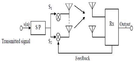
The basic concept of spatial multiplexing is to divide (multiplex) and transmit a data stream into several branches and transmit via several (independent) channels in space and different bits are transmitted via different antennas. One of the key advantages of MIMO spatial multiplexing is the fact that it is able to provide additional data capacity thus providing capacity gain.
MIMO spatial multiplexing achieves this by utilizing the multiple paths and effectively using them as additional channels to carry data such that receiver receives multiple data at the same time. The tenet in spatial multiplexing is to transmit different symbols from each antenna and the receiver discriminates these symbols by taking advantage of the fact that, due to spatial selectivity, each transmit antenna has a different spatial signature at the receiver . This allows an increased number of information symbols per MIMO symbol. In any case for MIMO spatial multiplexing, the number of receiving antennas must be equal to or greater than the number of transmit antennas such that data can be transmitted over different antennas. Therefore the space dimension is reused or multiplexed more than one time. The data streams can be separated by equalizers if the fading processes of the spatial channels are nearly independent. Spatial multiplexing requires no bandwidth expansion and provides additional data bandwidth in multipath radio scenarios [2].
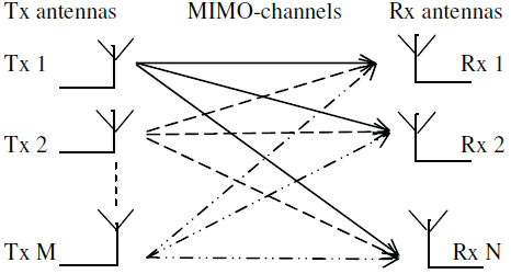
The general concept of spatial multiplexing can be understood using MIMO antenna configuration. In spatial multiplexing, a high data rate signal is split into multiple lower data rate streams and each stream is transmitted from a different transmitting antenna in the same frequency channel. If these signals arrive at the receiver antenna array with different spatial signatures, the receiver can separate these streams into parallel channels thus improving the capacity. Thus spatial multiplexing is a very powerful technique for increasing channel capacity at higher SNR values. The maximum number of spatial streams is limited by the lesser number of antennas at the transmitter or receiver side. Spatial multiplexing can be used with or without transmit channel knowledge.
2. MULTIPLE INPUT MULTIPLE OUTPUT (MIMO)
Multiple antennas can be used at the transmitter and receiver, an arrangement called a MIMO system. A MIMO system takes advantage of the spatial diversity that is obtained by spatially separated antennas in a dense multipath scattering environment. MIMO systems may be implemented in a number of different ways to obtain either a diversity gain to combat signal fading or to obtain a capacity gain. Generally, there are three categories of MIMO techniques. The first aims to improve the power efficiency by maximizing spatial diversity. Such techniques include delay diversity, STBC and STTC. The second class uses a layered approach to increase capacity. One popular example of such a system is V-BLAST suggested by Foschini et al. [2] where full spatial diversity is usually not achieved. Finally, the third type exploits the knowledge of channel at the transmitter. It decomposes the channel coefficient matrix using SVD and uses these decomposed unitary matrices as pre-and post-filters at the transmitter and the receiver to achieve near capacity [3]. Modulation is the process of mapping the digital information to analog form so it can be transmitted over the channel. Consequently every digital communication system has a modulator that performs this task. Closely related to modulation is the inverse process, called demodulation, done by the receiver to recover the transmitted digital information [4].
Modulation of a signal changes binary bits into an analog waveform. Modulation can be done by changing the amplitude, phase, and frequency of a sinusoidal carrier. There is several digital modulation techniques used for data transmission.
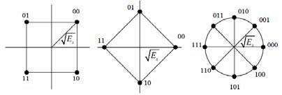
3. i. Phase Shift Keying (PSK)
Phase Shift Keying is a digital modulation scheme that conveys data by changing or modulating, the phase of a reference signal (the carrier wave). In Mary PSK modulation, the amplitude of the transmitted signals was constrained to remain constant, thereby yielding a circular constellation. Modulation equation of M-PSK signal is: Wireless transmission uses air or space for its transmission medium. The radio propagation is not as smooth as in wire transmission since the received signal is not only coming directly from the transmitter, but the combination of reflected, diffracted, and scattered copies of the transmitted signal.
( ) = 2 cos 2 + 2(Reflection occurs when the signal hits a surface where partial energy is reflected and the remaining is transmitted into the surface. Reflection coefficient, the coefficient that determines the ratio of reflection transmission, depends on the material properties.
Diffraction occurs when the signal is obstructed by a sharp object which derives secondary waves. Scattering occurs when the signal impinges upon rough surfaces, or small objects. Received signal is sometimes stronger than the reflected and diffracted signal since scattering spreads out the energy in all directions and consequently provides additional energy for the receiver which can receive more than one copies of the signal in multiple paths with different phases and powers. Reflection, diffraction and scattering in combination give birth to multipath fading.
4. i. AWGN Channel
Additive white Gaussian noise (AWGN) channel is universal channel model for analyzing modulation schemes. In this model, the channel does nothing but add a white Gaussian noise to the signal passing through it. This implies that the channel's amplitude frequency response is flat (thus with unlimited or infinite bandwidth) and phase frequency response is linear for all frequencies so that modulated signals pass through it without any amplitude loss and phase distortion of frequency components. Fading does not exist. The only distortion is introduced by the AWGN. AWGN channel is a theoretical channel used for analysis purpose only. The received signal is simplified to:
r(t)=s(t)+n(t)(2)where n(t) is the additive white Gaussian noise.
XIII Issue XI Version I
5. ( )
ii. Rayleigh Channel
Constructive and destructive nature of multipath components in flat fading channels can be approximated by Rayleigh distribution if there is no line of sight which means when there is no direct path between transmitter and receiver. The received signal can be simplified to:
r(t)=s(t)*h(t)+n(t)(3)where h(t) is the random channel matrix having Rayleigh distribution and n(t) is the additive white Gaussian noise. The Rayleigh distribution is basically the magnitude of the sum of two equal independent orthogonal Gaussian random variables and the probability density function (pdf) given by
p(r) = r 2 e r 2 2 2 0 (4)where 2 is the time-average power of the received signal.
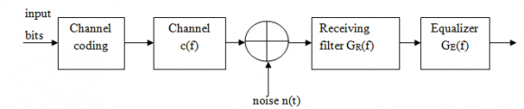
6. c) Signal Detection Techniques
There are numerous detection techniques available with combination of linear and non-linear detectors. The most common detection techniques are ZF, MMSE and ML detection technique. The generalized block diagram of MIMO detection technique is shown in Figure 4. The ZF is a linear estimation technique, which inverse the frequency response of received signal, the inverse is taken for the restoration of signal after the channel. The estimation of strongest transmitted signal is obtained by nulling out the weaker transmit signal. The strongest signal has been subtracted from received signal and proceeds to decode strong signal from the remaining transmitted signal. ZF equalizer ignores the additive noise and may significantly amplify noise for channel.
The basic Zero force equalizer of 2x2 MIMO channel can be modeled by taking received signal 1 during first slot at receiver antenna as:
y 1 = h 1,1 x 1 + h 1,2 x 2 + n 1 =[h 1,1 h 1,2 ]x 1 x 2 +n 1 (5) The received signal y 2 at the second slot receiver antenna is:
y 2 = h 2,1 x 1 + h 2,2 x 2 + n 2= [h 2,1 h 2,2 ]x 1 x 2 + n 2 (6) where i=1, 2 in x i is the transmitted symbol and i=1, 2 in h i, j is correlated matrix of fading channel, with j represented transmitted antenna and i represented receiver antenna, is the noise of first and second receiver antenna. The ZF equalizer is given by:
W ZF = (H H ) 1 H H (7)Where W ZF is equalization matrix and H is a channel matrix. Assuming M R and H has full rank, the result of ZF equalization before quantization is written as:
y ZF = (H H H) 1 H H y (8)ii. Minimum Mean Square Estimator Minimum mean square error equalizer minimizes the mean-square error between the output of the equalizer and the transmitted symbol, Instead of removing ISI completely; an MMSE equalizer allows some residual ISI to minimize the overall distortion. Compared with a ZF equalizer, an MMSE equalizer is much more robust in presence of deepest channel nulls and noise. The MMSE equalization is:
W MMSE = arg G min E x,n [ x x ^ 2 ] (9)Where is W MMSE equalization matrix, H channel correlated matrix and n is channel noise 2 presents that at 32-PSK, 1024-PSK there is an improvement of 9dB, at 64-PSK, 128-PSK, 256-PSK there is an improvement of 8dB and at 512-PSK there is an improvement of 6dB at BER of 10 -4 . Hence table shows the improvement in terms of decibels shown by proposed system employing SM technique for 2x2 MIMO system for different modulation schemes over different channels.
y MMSE = H H (HH H + n o I n ) 1 y(IV.
7. CONCLUSION
In this paper, an idea about the performance of the MIMO-SM technique at higher modulation levels and for 2x2 antenna configuration using different signal detection technique is presented. MIMO-SM technique can be implemented using higher order modulations to achieve large data capacity. But there is a problem of BER (bit error rate) which increases as the order of the modulation increases. The solution to this problem is to increase the value of the SNR so, that the effect of the distortions introduced by the channel will also goes on decreasing, as a result of this, the BER will also decreases at higher values of the SNR for high order modulations.

| for Rayleigh & AWGN Channel for 2x2 MIMO Spatial | |||
| Multiplexing using ZF Equalization | |||
| Modulations | Rayleigh Channel | AWGN Channel | Improvement |
| 32-PSK | 65dB | 57 dB | 8 dB |
| 64-PSK | 71 dB | 64 dB | 7 dB |
| 128-PSK | 77 dB | 69 dB | 8 dB |
| 256-PSK | 84 dB | 76 dB | 8 dB |
| 512-PSK | 90 dB | 82 dB | 8 dB |
| 1024-PSK | 96 dB | 87 dB | 9 dB |
| Modulations | Rayleigh Channel | AWGN Channel | Improvement |
| 32-PSK | 65dB | 56 dB | 9 dB |
| 64-PSK | 72 dB | 64 dB | 8 dB |
| 128-PSK | 77 dB | 69 dB | 8 dB |
| 256-PSK | 83 dB | 75 dB | 8 dB |
| 512-PSK | 88 dB | 82 dB | 6 dB |
| 1024-PSK | 96 dB | 87 dB | 9 dB |
| Table |