1. Introduction
oltage unbalance combined with under-or over voltage is a voltage quality problem. The mentioned phenomenon can be found in a threephase power system commonly. Different factors cause unbalanced voltage in power system including unbalanced loads, incomplete transposition of transmission lines, open-Y, open-Î?" transformer connections, blown fuses on three-phase capacitor banks and etc. The induction motors are widely used in industrial, commercial and residential applications and most of them are connected directly to electric power distribution system (PDS). Therefore it is very important to clarify the effect of voltage unbalance on the performance of IM (Hirotsuka et al., 2006).
The unbalanced voltages induces negative sequence current and mentioned current produces a backward rotating field in addition to the forward rotating field produced by the positive sequence one. The interaction of these fields produces pulsating electromagnetic torque and ripple in velocity (Alwash and Ikhwan, 1995;Smith and Dorrell, 1996) Such condition has severe impacts on the performance of an induction motor.
The in fluence of unbalance on the efficiency (Lee, 1999), increase of losses, and the negative effects on the insulation life (Gnaci´nski, 2008), temperature rise, and life reduction (Pillay and Manyage, 2006), derating in the machine (Anwari and Hiendro, 2010) are some contributions in this area.
2. II.
3. Different Definitions of Voltage Unbalance in Standards
There are three general definitions for measuring the voltage unbalance in standards. The first definition is LV U R , given by NEMA, is as follow (NEMA MG 1, 2003):
[ ] max , ,100ab avg bc avg ca avg avg V V V V V V LVUR V ? ? ? = ×(1)In (1) V ab , V bc and V ca are line -to -line voltages.
3 ab bc ca avg V V V V + + = (2)The second definition for voltage unbalance has been given by the IEEE Std 141 is PVUR as follow:
max , ,100a avg b avg c avg avg V V V V V V PVUR V ? ? ? ? ? ? ? = ×(3)Where
100 3 a b c avg V V V V + + = ×(4)In (3) V a , V b and V c are phase voltages.
And The third definition is Voltage unbalance factor (VUF) has been given by IEC (Lee, 1999; Anwari and Hiendro, 2010):
2 1 100 V VUF V = ×(5)Where, V 1 and V 2 represent the positive and negative sequence phase voltage components that they can be calculated with the application of the Fortescue transformation in the complex plane, as follow:
0 2 1 2 2 1 1 1 1 1 3 1 a b c V V V a a V a a V V ? ? ? ? ? ? ? ? ? ? ? ? = ? ? ? ? ? ? ? ? ? ? ? ? ? ? ? ? ? ? V - F obal Journal of Researches in Engineering Gl -(6)Where
(2 / 3) j a e ? =is the Fortescue operator. The VUF then calculated as in (5).
4. III.
5. Different Types of Voltage Unbalance
For this article, VUF selected to use. But this is significant they are many unbalanced voltages possible with the same voltage unbalance factor. In the present work following six different unbalanced cases are considered (Lee, 1999):
(1) Single phase over-voltage unbalance (1?-OV) (2) Two phase over-voltage unbalance (2?-OV) (3) Three phase over-voltage unbalance (3?-OV) (4) Single phase under-voltage unbalance (1?-UV) (5) Two phase under-voltage unbalance (2?UV) (6) Three phase under-voltage unbalance (3?UV) A wide variety of research has been done on modeling of unbalanced condition in study of induction machines. In the unbalanced voltage operating condition the torque can be written as follow (Xu and Wang, 2007):
0 2 0 2 ( ) P P P T T T ? ? + = = = +(7)Where, T 0 is the DC torque and T 2 is the torque component which frequency is twice the supply frequency. In a simpler way assuming induction motor as a RL load the torque can be written as:
V I T ? ? × × =(8)In which V and I are input voltage and current of each phase respectively. Assuming sinusoidal waveforms for voltage and current this equation can be rewritten as follow:
cos(2 ) cos(2 ) T K f f ? ? ? ? = + + (9) So, [ ] ' cos( ) cos(4 ) T K f ? ? ? ? ? = ? + + +(10)Based on equation (10) the resulting torque would include a DC term and a term which frequency is twice the fundamental frequency of the applied voltage. In order to detect the unbalanced supply voltage this extra torque component can be used.
6. V.
7. Using FEM
In this section authors introduced briefly about procedure of induction motor simulation using finite element method.
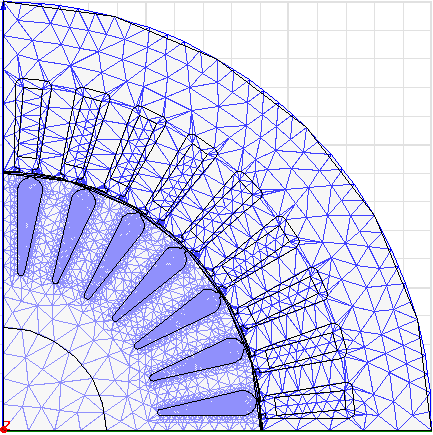
a) Analysis Model Table I and Fig. 1 show the technical data of the analyzed motor and also, its meshed quarter cross section, respectively. b) Time-Stepping 2D FEM At the present study, time-stepping FEM is used for the analysis performance of mentioned induction machine. The dynamic equations of the induction machine can be written as follow (Krause, 1986):
i i i d V RI dt ? = +(11)In (11), I and V are current and voltages of the three phase stator windings, respectively. ? i and R are the matrices of the phase flux linkage and stator winding resistances.
The dynamic equation of mechanical system of machine is (Krause, 1986):
LOAD m d T T J B dt ? ? ? = +(12)8. Theoretical Aspects of the Electromagnetic Torque under Unbalanced Condition
In order to realize the variations of the load for simulated motor, a linear load torque with the following equation is considered as the load:
FL LOAD r rated T T ? ? ? ? = × ? ? ? ?(13)In (13), TFL is full load torque, ? r , ? rated are speed and rated speed, respectively.
The used voltages (and their positive and negative sequence components) in performance simulation of motor under unbalanced voltage condition are listed in Table II. These voltages are selected so that their VUF is similar and equal to 6%. Transient solver with step time equal to 0.1 ms is used in simulations. Quarter cross section of motor meshed with 9688 triangles. Simulation of each cycle (20ms) using 3GHz core 2do CPU and 2 Giga Byte of DDR2 Ram, consumed 236.3 seconds of time.
9. VI.
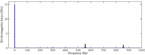
Result and Discussion a) Balanced Condition Fig. 2 shows the electromagnetic torque of the simulated induction motor in time domain when supply voltage is balanced. This toque in frequency domain is showed in Fig. 3. The frequency analysis has been made using FFT. Ripple in torque waveform in time domain or in other words, torque components except DC component in frequency domain are mainly due to teeth slot effect. Skew is applied to electrical machines in order to reduce undesirable teeth slot effects such as cogging torques, higher-harmonic air-gap fields, torque ripple, vibrations, and noise (De Gersem et Al., 2003). But applied skew will be ignored in simulation using two dimensional finite element method therefore it can be expected that calculated ripple due to teeth slot effect is higher than corresponding value in the real skewed machine. However, ignoring the skew has not any significant error in study of the performance of electrical machines and 2D FEM is widely used in this area
10. b) Unbalanced Condition
The electromagnetic torque of the motor under an unbalanced case (2?-OV) has been shown in Fig. 4. Fig. 5 shows the mentioned torque in frequency domain. According to this figures, there is a 100 Hz component Where T, T LOAD , ?, J and B m are electromagnetic moving torque, load torque, velocity of the rotor, total moment of inertia of rotor and load, and damping, respectively.
3?
11. Conclusions
In this paper, performance of a three phase induction motor under six types of unbalanced voltages with same VUF has been simulated using 2D FEM and also, studied electromagnetic torque of the motor in this condition. It is seen that both average torque and torque ripple increase with increasing positive sequence voltage component for considered types of unbalanced voltages. Even in case of unbalanced voltages combined with over voltage in one or more phases, average torque exceeded from equal value in balanced case. Authors emphasized to detect unbalance condition, torque frequency analysis can be used.
12. XIII Issue IX Version I
13. ( )
14. Year
15. References Références Referencias
Three-Phase Induction Motor's Torque under Voltage Unbalance with significant value in motor's torque as expected. Fig. 6 shows DC term and 2nd harmonic order of electromagnetic torque how change when induction motor supposed balanced and six various types of unbalanced voltages with same VUF equal to 6% as before mentioned. It can be seen in considered six types of unbalanced voltages, both average torque and 2nd harmonic order increase with increasing positive sequence voltage component. According to Fig. 6, the unbalanced voltages does not always lead to reduced average torque of motor, even in case of unbalanced voltages combined with over voltage in one or more phases, average torque exceeded from equal value in balanced case. But this increase is not desirable because it would be associated with increased power losses and reduced efficiency (Lee, 1999). Note that when 2nd harmonic order of torque increases, ripple in velocity will increase. In other words, ripple in velocity increase with increasing positive sequence voltage component, also. The mentioned ripple in torque and velocity can be used to detect the unbalanced supply voltage for the induction motors that they may suppose unbalanced voltages.

| Item | Value | Item | Value |
| Input Voltage(V) | 380 | Stator outer | 150 |
| diameter(mm) | |||
| Output | 2.2 | Rotor outer | 90 |
| Power(kW) | diameter(mm) | ||
| Frequency (Hz) | 50 | Core length(mm) | 90 |
| Rated current(A) | 5.3 | Air gap(mm) | 0.3 |
| Pole number | 4 | Stator lamination | M530- |
| type | 50A | ||
| Rated | 1410 | Rotor lamination | M530- |
| speed(rpm) | type | 50A | |
| Connection | Y | No. turns in stator | |
| coil |
| Analytical | ||||
| model. | IEE | Proceedings | Electric | Power |
| Applications, 143(3): 193-201. | ||||