1. Introduction
igh speed communications over broadband wireless channels has emerged as a key feature of future communications systems due in part to the explosive interest in information technology applications, including wireless networks, mobile computing, high speed mobile internet, and video transmission over wireless channels. The demand for higher information capacity in these and other similar applications has motivated the use of broadband wireless channels in order to provide wider bandwidth and higher data rates.
OFDM is a widely recognized modulation technique for high data rate communications over wireless links. Because of its capability to capture multipath energy and eliminate inter-symbol interference, OFDM has been chosen as the transmission method for several standards, including the IEEE 802.11a wireless local area network (WLAN) standard in the 5-GHz band, the IEEE 802.11g WLAN standard in the 2.4-GHz band. Also, the OFDM-based physical layer is being considered by several standardization groups, such as the IEEE 802.15.3 Author ? : IIET, Kinana (Jind), Haryana, India. Author ? : Govt. P.G. College, Jind, Haryana, India. E-mails : [email protected] , [email protected] wireless personal area network (WPAN) and the IEEE 802.20 mobile broad-band wireless access (MBWA) groups. The heightened interest in OFDM has resulted in tremendous research activities in this field to make the real systems more reliable and less costly in practice.
OFDM has been practically implemented in the United Kingdom in the form of digital Video broadcasting-Terrestrial (DVB-T) for quiet sometime now and it has been found useful there. In addition to that earlier this year this technology has given birth to a new concept known as "telemedicine" where doctor and patient can be in different parts of the globe but the patient can still consult the doctor. There can be nothing more to humanity! This is made possible by the high speed data transfer offered by this technique. We feel OFDM is a potential candidate for the physical layer of 4G mobile communication.
2. II.
3. Niceties a) Channel Modeling
In order to evaluate the effectiveness of a given channel coding and processing technique before actual implementation, some model of the channel must be developed that adequately describes the environment. Such analysis reduces the cost of developing a complex system by reducing the amount of hardware that has to be developed for evaluation of performance. By examining the details of how a signal is propagated from a transmitter to a receiver, we can effectively generate a better hardware of transmitter and receiver as physical processes can be judged which modify the transmitted signal.
It is usually described by three components: An input alphabet, an output alphabet and a transition probability 'p' (i,o).
4. b) Multipath Fading
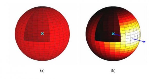
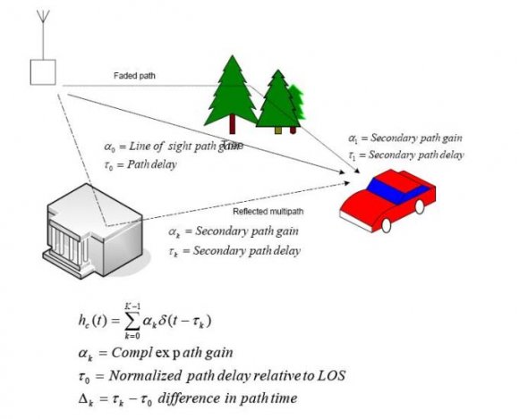
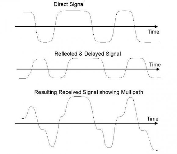
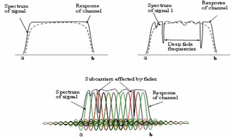
Modern During propagation, radio signals weaken with distance. This is due to the wave front of the radio signal expanding and thus reducing in power density. In free space, the propagating wave expands as a sphere and thus the power density reduces in proportion to the surface area of this sphere. If the signal is transmitted using a directional antenna, the signal still expands as a sphere, except that the energy density is concentrated to one or more areas (see If the path from the transmitter to receiver either has reflections or obstructions, we get fading effects. In this case, signal reaches the receiver from many different routes, each a copy of original. Each of these rays, called multipath signals/waves, has a slightly different delay and slightly different gain. This results in either constructive or destructive interference, amplifying or attenuating the signal power at receiver. Strong destructive interference is frequently referred to as a deep fade and thus SNR drops significantly.
5. d) Delay Spread
Delay spread is a measure of the spread in the time over which the multipath signals arrive. It is a measure of the time dispersion of a channel, and is very important in determining how fast the symbol rate can be in digital communications. A symbol is a period over which one or more groups of bits of information are sent. For a single carrier transmission, using Binary Phase Shift Keying (BPSK) as the modulation scheme, each symbol carries one bit of information. The symbol corresponds to the period required to send the phase information as 0° or 180°, which corresponds to the digital information of zero or one respectively. The faster the phase is varied the faster the symbol rate and the higher the data rate and bandwidth. For OFDM transmission, each symbol corresponds to a parallel transmission of many low bandwidth carriers. The symbol time in this case corresponds to the period over which the amplitude and phase of the data carriers is remained fixed corresponding to one data vector. Delay spread results in time blurring, where energy from previous data symbols becomes mixed in with current symbols. This causes interference, known as Inter-Symbol Interference (ISI), because previous symbols are uncorrelated, effectively adding noise to the signal. Single carrier transmissions are particularly prone to problems caused by delay spread as it normally sets the upper limit on symbol rate. This is because the bit error rate (BER) increases as the delay spread time becomes a significant fraction of the symbol time. Simple modulation schemes such as BPSK can tolerate a delay spread of approximately 10 -20% of the symbol period; anymore and the BER is too high.
However, higher modulation schemes such as 16-QAM, 256-QAM, etc, which have a higher spectral efficiency, are much more sensitive to ISI and thus the delay spread must be less than several percent of the symbol period.
6. e) Equalization
One method to overcome the limitations of delay spread for single carrier transmission is to use equalization. The aim of equalization is to find an inverse filter that compensates for the ISI so that all the multipath signals become shifted and aligned in time, rather than being spread out. For example, the GSM phone system, which uses 270 k symbols/s (3.7 ms symbol period), can tolerate a delay spread of up to 15 ms. This is a delay spread of over four symbol periods. frequency domain so that the width of the subcarriers is much narrower than frequency selective fading of the radio channel. This makes the frequency response over the bandwidth of each subcarrier effectively flat. Only simple equalization is required for each subcarrier for data transmission as the flat fading on each subcarrier only results in an amplitude scaling and a phase rotation. For coherent transmissions, equalization is implemented by transmitting reference pilot symbols or tones, which are set to an amplitude and phase known by both the transmitter and receiver. The channel response is then estimated by dividing the received subcarrier IQ vector of the pilot symbol or tone by the known transmitted vector. This measured channel response is then used to equalize the transmitted data. No equalization is needed for transmissions using differential phase modulation. With this method, the amplitude of the subcarrier is not used for carrying information and so its value is not important. With differential phase modulation the data is transferred as a phase difference between successive symbols. This compensates for any phase offset caused by the propagation channel.
7. Global Journal of Researches in Engineering
8. f) Principle of OFDM System
OFDM is a parallel transmission scheme, where a high-rate serial data stream is split up into a set of low rate substreams, each of which is modulated on a separate SC (FDM). Thereby, the bandwidth of the SCs becomes small compared with the coherence bandwidth of the channel; that is, the individual SCs experience flat fading, which allows for simple equalization.
This implies that the symbol period of the substreams is made long compared to the delay spread of the time-dispersive radio channel. By selecting a special set of (orthogonal) carrier frequencies, high spectral efficiency is obtained because the spectra of the SCs overlap, while mutual influence among the SCs can be avoided.
The derivation of the system model shows that by introducing a cyclic prefix, the orthogonality can be maintained over a dispersive channel.
9. g) Orthogonality
Orthogonal Frequency Division Multiplexing (OFDM) is a multicarrier transmission technique, which divides the available spectrum into many carriers, each one being modulated by a low rate data stream. In Communications, multiple-access schemes are orthogonal when an ideal receiver can completely reject arbitrarily strong unwanted signals using different basis functions than the desired signal. One such scheme is TDMA, where the orthogonal basis functions are nonoverlapping rectangular pulses ("time slots"). Another scheme is orthogonal frequency-division multiplexing (OFDM), which refers to the use, by a single transmitter, of a set of frequency multiplexed signals with the exact minimum frequency spacing needed to make them orthogonal so that they do not interfere with each other.
Well known examples include a and g versions of 802.11 Wi-Fi; Wimax; ITU-T G.hn, DVB-T, the terrestrial digital TV broadcast system used in most of the world outside North America; and DMT, the standard form of ADSL.
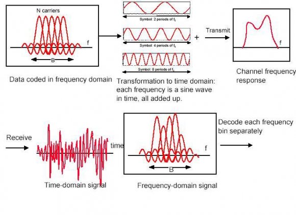
One major limitation faced by OFDM is its high sensitivity to phase noise introduced by local oscillators. Phase noise is the phase difference between the phase of the carrier signal and the phase of the local oscillator. The distortion caused by this phase noise is characterized by a CPE term and an ICI term. CPE term represents the common rotation of all constellation points in the complex plane, while the ICI term behaves like AWGN. The transmitter section converts digital data to be transmitted, into a mapping of subcarrier amplitude and phase. It then transforms this spectral representation of the data into the time domain using an Inverse Discrete Fourier Transform (IDFT). The Inverse Fast Fourier Transform (IFFT) performs the same operations as an IDFT, except that it is much more computationally efficiency, and so is used in all practical systems. In order to transmit the OFDM signal the calculated time domain signal is then mixed up to the required frequency. The receiver performs the reverse operation of the transmitter, mixing the RF signal to base band for processing, then using a Fast Fourier Transform (FFT) to analyze the signal in the frequency domain. The amplitude and phase of the subcarriers is then picked out and converted back to digital data. The IFFT and the FFT are complementary function and the most appropriate term depends on whether the signal is being received or generated. In cases where the signal is independent of this distinction then the term FFT and IFFT is used interchangeably.
10. Global Journal of Researches in Engineering
11. j) Interleaving
Let's understand this concept with the help of an example. Suppose there are four families (each having four members) going on a holiday in there four cars. In each of the cars there is exactly one family. Now if unfortunately a car meets with an accident then one whole family will be finished. But suppose if they were to be seated differently i.e. if each car had exactly one member of each family and then the accident were to happen then no single family would be finished. The loss would be equal for all the families. This is certainly better. Same is with our data. If we send our data this way then we can eliminate some noise effect like burst noise effect.
12. k) Cyclic Prefix
In an OFDM, the cyclic prefix is a repeat of the end of the symbol at the beginning. The purpose is to allow multipath to settle before the main data arrives at receiver. The receiver is normally arranged to decode the signal after it has settled because this is when the frequencies become orthogonal to each other. The length of cyclic prefix is equal to guard interval.
13. III.
14. System Overview
Wireless multi-carrier transmission system is based on Orthogonal Frequency-Division Multiplexing (OFDM) including a simple channel coding scheme for error correction and interleaving across subcarriers for increased frequency diversity. a) Some Assumptions
15. ? Usage of Cyclic Prefix
? Impulse response of the channel shorter than cyclic prefix.
? Slow fading effects so that the channel is time invariant over the symbol interval.
? Rectangular windowing of the transmitted pulses.
? Perfect Synchronization of transmitter and receiver.
? Additive, White, Gaussian Noise channel.
? Data Rate of OFDM signal: 1Mbps/carrier
? Guard Length: 16 IV.
?16. Findings
We obtained the following graphical results: V.
17. Conclusion
The results show that using QPSK the transmission can tolerate a SNR of >10-12 dB. The bit error rate BER gets rapidly worse as the SNR drops below 6 dB. However, using BPSK allows the BER to be improved in a noisy channel, at the expense of transmission data capacity. Using BPSK the OFDM transmission can tolerate a SNR of >6-8 dB. In a low noise link, using 16PSK can increase the capacity. If the SNR is >25 dB 16PSK can be used, doubling the data capacity compared with QPSK.
The simulations shown above calculated the signal to noise ratio based on the power of the time domain signal waveform and the power of the time domain noise waveform, with no consideration of the signal bandwidth. At the receiver the signal is filtered by the FFT stage, thus making the receiver only see noise within the signal bandwidth. The simulations were performed using 800 carriers and generated using a 2048-point IFFT. The nyquist bandwidth is half the transmission sample rate as the signal is real (i.e. no imaginary components) and so the nyquist bandwidth corresponds to 1024 carriers. The signal bandwidth is thus 800/1024 = 0.781 or 78.1% of the nyquist bandwidth. Since the receiver was only seeing 78.1% of the total noise the error rate is lower than it should be. The correct SNR values can be found by adding 1.07 dB (10log10(0.781)) to the scale in Figure (f).
Also we noted down that to achieve the same BER performance, SNR must be higher. SNR performance loss reduces almost proportionally with number of pilot tones, thus the loss when using 4 pilot tones is 4 times lower (in db).