1. Introduction
he future of hypersonic air-breathing vehicles lies in the successful development and design of Supersonic combustion ramjet (SCRAMJET) engines which poses some major challenges that has attracted the attention and imagination of researchers worldwide. The serious issues like fuel-air mixing, flame holding, pressure losses and thermal loading can be resolved with the successful implementation of a fuel injection system that provides rapid mixing between the fuel and oxidizer streams, induces pressure losses to a minimum with reduced or zero adverse effects on flame holding capability or thermal/structural integrity of the device. A very short time for fuel injection, fuel-air mixing and subsequently combustion is available of the order of 1 ms and hence the increasing need to develop a system that effectively integrates fuel injection and flame holding for supersonic combustion exists. Thus cavity flame holders has been proposed in recent years as a new concept for flame holding and stabilization in supersonic combustors [4].
Some recent publications have brought to light the subject of cavity flows and their relevance to flame holding in supersonic combustion engines [1,2,3].Lowspeed combustion studies with an axis symmetric cavity [5]found optimum flame holding performance using a cavity with its length-to-depth ratio L=D sized for the minimum aerodynamic drag. Longer cavities produced vortex shedding that resulted in unstable flames, and shorter cavities did not provide enough air entrainment to hold the flame. Experimental and numerical results were show n to agree closely on this point [6]. Cavities with small aspect ratios provide better flame holding capability than longer cavities with aft ramp angles as suggested in a study by Yu et al [7] where fuel was injected upstream of a variable L/D cavity at flow speed of Mach 2.
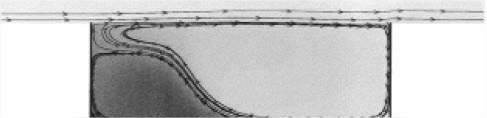
A configuration having a baseline fuel injector/ flame holder with a low angled fuel injection upstream of a wall cavity was used by Tarun Mathur et al [8] where fuel injection and flame piloting was done in a scramjet combustor with all the components contained in the wall. In contrast to in-stream concepts that introduce additional friction drag, wave drag, and cooling requirements to the combustor, this configuration uses no in-stream devices, thereby minimizing these detrimental effects and simplifying the overall combustor and system designs. Similar studies which involves flush-wall injection upstream of similar cavities in non reacting supersonic flow have provided valuable insights into the effects of cavity configuration (L=D ratio, offset ratio, aft ramp angle), fuel injection pressure, and imposed back pressure on drag, residence times, and fuel distribution within the cavity [9,10]. The combustion experiments as described by Tarun Mathur et al [8] as well as some numerical simulations of cavity-based fuel injector/flame holder [11,12,13] have shown robust flame holding and combustion performance in a scramjet combustor simulating Mach 4-6 conditions at a dynamic pressure of 47.9 k Pa. Some difficulties associated with hydrocarbon fuels which primarily include the relatively long ignition delay time and the challenge in diffusing stable combustion energy into the main flow without disturbing the flow and creating drag penalties may be tackled by cavity-based flame holders as suggested by Ben Yakar et al [2].A cavity-based flame holder a) creates a sheltered subsonic recirculation area of hot combustion products and increases the effective residence time for the fuel, and b) acts as a pilot light to spread hot combustion products into the main flow. The flow in the vicinity of the cavity can be very stable and can limit the amount of mass entrainment. As can be seen from the fig. 1 below which is a result of numerical computations by Gruber et al [10] there are trapped vortices within the cavity, including a large primary recirculation zone that interacts with the free stream, and a smaller fuel-rich secondary vortex in the forward corner of the cavity. The Cavity flow regimes has been categorized basically into two types by Ben Yakar et al [14] that depends primarily on length-to-depth ratio, L/D. In all the cases it is seen that a shear layer gets separated from the upstream lip and get reattached downstream. The reattachment takes place in the back face for L/D< 7-10 and hence are termed as open. For L/D< 2-3 transverse oscillation mechanism plays the dominant role but large aspect ratio cavities are controlled by longitudinal oscillations.The high pressure at the rear face as a result of the shear layer impingement increases the drag of the cavity. For L=D >10-13 the cavity flow is termed "closed" because the free shear layer reattaches to the lower wall. The pressure increase in the back wall vicinity and the pressure decrease in the front wall results in large drag losses. The critical length-to-depth ratio, at which a transition between different cavity flow regimes occurs, depends also on the boundary-layer thickness at the leading edge of the cavity, the flow Mach number, and the cavity width.
Another way of improving fuel the fuel-air mixture within the cavity can be direct fuel injection into the cavity as investigated by Allen et al [15]. This resulted in decreased size of fuel rich vortex with subsequent improvement in combustion within the cavity which was due to improved fuel air mixture because of additional air injected directly into the cavity. They also observed that the air injection technique did not have merely a undeviating effect on the fuel-rich region, in fact increasing the air injection without bound had diminishing effect, and eventually are verse effect. For lower fuel injection rates, if the air injection was increased to its maximal limit the combustion increases seen at lower air injection rates moderated to levels near the original fuel-only case. It would seem that the direct air injection technique is able to cause the cavity fuel-air mixture to become too lean to gain any enhancements in combustion if the air injection rate is not organized.
2. II.
3. Materials and Methods
4. a) Physical Model
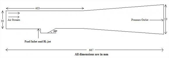
A mathematical model consists of equations concerning the dependent and the independent variables and the relevant parameters that describe some physical phenomenon. In general, a mathematical prototype consists of differential equations that govern the performance of the physical system, and the related boundary conditions which is shown in figure 2. The advantage of employing the complete Navier-Stokes equations extends not only the investigations that can be carried out on a wide range of flight conditions and geometries, but also in the process the location of shock wave, as well as the physical characteristics of the shock layer, can be exactly determined. We begin by describing the threedimensional forms of the Navier-Stokes equations below. Note that the two-dimensional forms are just simplification of the governing equations in the three dimensions by the omission of the component variables in one of the co-ordinate directions. Neglecting the presence of body forces and volumetric heating, the three-dimensional Navier-Stokes equations are derived as [16]: Continuity Equation: (5) Assuming a Newtonian fluid, the normal stress ? xx , ? yy and ? zz can be taken as combination of the pressure p and the normal viscous stress components ? xx , ? yy , and ? zz while the remaining components are the tangential viscous stress components whereby ? xy = ? yx , ? xz = ? zx , and ? yz = ? zy . For the energy conservation for supersonic flows, the specific energy, E is solved instead of the usual thermal energy H applied in subsonic flow problems. In three dimensions, the specific energy E is repeated below for convenience: E= e +
5. ????
It is evident from above that the kinetic energy term contributes greatly to the conservation of energy because of the high velocities that can be attained for flows, where Ma>1.Equations ( 1)-( 6) represent the form of governing equations that are adopted for compressible flows. The solution to the above governing equations nonetheless requires additional equations to close the system. First, the equation of state on the assumption of a perfect gas unemployed, that is,
6. P= ? R T
where R is Gas constant Second, assuming that the air is calorically perfect, the following relation holds for the internal energy:
e= C v Twhere C v is specific heat at constant volume. Third, if the Prandtl number is assumed constant (approximately 0.71) for calorically perfect air), the thermal conductivity can be evaluated by the following: The Sutherland's law is typically used to evaluate viscosity ?, which is provided by:
?? = ?? 0 ? ?? ?? 0 ? 1.5 ?? 0 +120 ??+120(7)Where ? 0 and T 0 are the reference values at standard sea level conditions
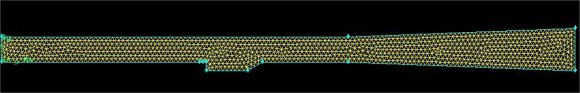
7. Computattional and Model Parameters a) Geometry and mesh generation
Mesh generation was performed in a Fluent preprocessing program called Gambit. The current model is cavity-based fuel injector with non-premixed combustion as shown in figure 3. The boundary conditions are such that, the air inlet and fuel inlet surfaces are both defined as pressure inlets and the outlet is defined as pressure outlet. Recent research has revealed that perhaps the numerical model will improve if the air inlet is defined as pressure inlet and the fuel inlet is defined as a mass flow inlet. In this particular model the walls of the combustor duct do not have thicknesses. The domain is completely contained by the combustor itself; therefore there is actually no heat transfer through the walls of the combustor. During analysis we have taken same pressure for both fuel and air for all the models. Pressure inlet and pressure outlet conditions were taken on the left and right boundaries respectively. Pressure inlet condition was taken for fuel injector. The top and bottom boundaries, which signify the sidewalls of the isolator, had symmetry conditions on them. The walls, obstacles and other materials were set to standard wall conditions. The computations were initially carried out with various levels of refinement of mesh. There exists a definite level of refinement beyond which there is no significant quantitative change in the result. The limit of that refinement is called the Grid Independent Limit (GIL). The input parameters that were for the model is shown in tabulated form.
8. c) Modeling Details
In the CFD model, the Standard k-??turbulent model is selected which is one of the most common turbulence models. It is a two equation model that means it includes two extra transport equations to represent the turbulent properties of the flow. This two equation model accounts for history effects like convection and diffusion of turbulent energy. Further, because of the intense turbulent combustion, the eddydissipation reaction model is adopted. The eddydissipation is based on the hypothesis of infinitely fast reactions and the reaction rate is controlled by turbulent mixing. Both the Arrhenius rate and the mixing rate are calculated and the smaller of the two rates is used for the turbulent combustion. While no-slip conditions are applied along the wall, but due to the flow being supersonic, at the outflow all the physical variables are extrapolated from the internal cells. Energy equations were considered and the solution was initialized from the air inlet for simplicity. For hydrogen-air mixing, ideal gas mixing law was followed for determination of thermal conductivity and viscosity, while density was assumed to be for ideal gas. Mass diffusivity was assumed to be following kinetic theory.
IV.
9. Results and Discussions
The various plots of properties such as static temperature, densities etc. along the length of the combustor for the different models are given below. The red colored regions are the regions where the properties attain their maximum values. The blue colored regions indicate the regions where the properties are at their minimum. The properties that were analyzed were: The static temperature was taken as an indication of combustion efficiency of the fuel (hydrogen). Higher combustion efficiency means a greater percentage of the injected fuel undergoes combustion resulting in a higher static temperature at the combustor exit. Study of the mass fraction contours of H2, O2 and H2O showed evidence of fuel injection, air fuel mixing and combustion respectively. The presence of H2O indicated the occurrence of combustion. Turbulent kinetic energy was an indication of vortex formation in the cavity which enhances air-fuel mixing. The X-velocity was the velocity at which the combustion products exit the combustor. It represented the thrust available for propulsion of the scramjet. The static pressure and density contours and static pressure and density graphs help in visualizing the shock waves produced by the velocity of hydrogen injection. Moreover, interaction of the reflected shock waves with the air-fuel mixing boundary (visible in the density and static pressure contours) further enhanced the mixing and promoted.
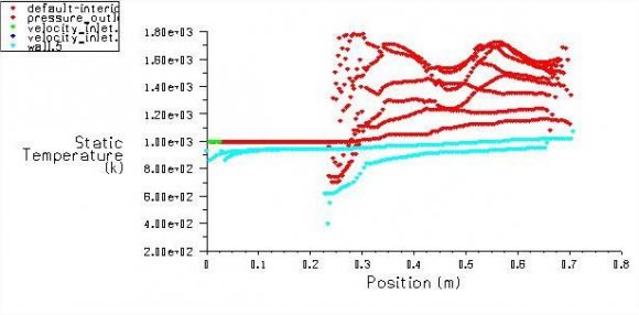
10. a) Static Temperature
From Fig 4 it is evident that static temperature increases from inlet to the outlet. This is due to combustion of the air and injected H2 fuel. The heat released due to combustion heats up the combustion products (water) and hence, an increase in the static temperature from 398K to 1789 K is observed. The below graph shows the distribution of H 2 in the interior of the combustor. As can be seen, the mass fraction of hydrogen is maximum at the fuel injection port and continues to decrease along the length of the combustor due to combustion. Thus, the graph provides evidence of combustion. Typically, when dealing the chemical reaction, it's important to remember that mass is conserved, so the mass of product is same as the mass of reactance. Even though the element exists in different the total mass of each chemical element must be same on the both side of equation. The contour and XY Plot of O 2 Mass fraction for the flow field downstream of the injector is shown in the figure 12 and figure 13. Oxygen is increased in every combustion reaction in combustion applications and air provides the required oxygen. All components other than air collected together with nitrogen. In air 21% of oxygen and 79% of nitrogen are present on a molar basis. From the figure 12 it is observed that, the maximum mass fraction of O 2 is 0.213 which is seen at the beginning of combustion. Figure 13 shows that the profile between the mass fraction of O 2 and the position of the combustion on all conditions such as air inlet, fuel inlet, pressure outlet, default interior and all walls. The contour of mass fraction of OH is shown in figure 14. From the figure 14 it is observed that, the maximum mass fraction of OH is 0.001454 which is found out after combustion, where the minimum value is 0. Figure 15 shows that the profile between the mass fraction of OH and the position of the combustion on all conditions such as air inlet, fuel inlet, pressure outlet, default interior and all walls.
11. Conclusion
The computational analysis of 2D cavity-based fuel injector was carried out with k-? turbulence model for exposing the flow structure of progress of hydrogen jet through the areas disturbed by the reflections of oblique shock. For that single step reaction kinetics has been used to model the chemistry. The k-? turbulence model also predicted the fluctuations in those regions where the turbulence is reasonably isotropic. From the maximum mass fraction of OH a very small amount of OH (1.45e-03) was observed after combustion. From the above analysis, it is observed that for a scramjet engine having a wall injector with a cavity of L/D=5, if hydrogen is injected at a speed of Mach 1.5 to an incoming air stream at Mach 3.12 speed, a rich air-fuel mixture can be achieved and efficient combustion of this mixture gives a maximum temperature of 1789K at the outlet of the combustor. Also, there is a weak shock formation. Hence, better flame holding can be achieved if the wall injector is coupled with a cavity having with an L/D ratio of 5. Due to ever increasing human need for greater speed and reduced travel time, hypersonic combustion systems will become more and more important in the future. As the mixing time for fuel in the combustor system is very less (~1ms), newer and better injection systems have to be developed that enhance fuel-air mixing and reduce ignition delay period, thus increasing both combustion efficiency and thrust.


| ?? | ???? ???? | + | ??(????) ???? | + | ??(????) ???? | + | ??(????) ???? | = | [ | ?? ?? ?? ?? ???? ???? ???? | ] | + | ??[ ?? ?? ?? ?? ???? ???? ???? | ] | + | ??[ ?? ?? ?? ?? ???? ???? ???? | ] | + (?? |