1. INTRODUCTION
ibration of aircraft steering systems has been a problem of great concern since the production of first airplanes. Shimmy is an oscillatory motion of the landing gear in lateral and torsional directions, caused by the interaction between the dynamics of the tire and the landing gear, with a frequency range of 10-30 Hz. Though it can occur in both nose and main landing gear, the first one is more common. Shimmy is a dangerous condition of selfexcited oscillations driven by the interaction between the tires and the ground that can occur in any wheeled vehicle. Problem of shimmy occurs in ground vehicle dynamics and aircraft during taxiing and landing. In other words, shimmy takes places either during landing, take-off or taxi and is driven by the kinetic energy of the forward motion of the aircraft. It is a combined motion of the wheel in lateral, torsional and longitudinal directions.
2. II.
3. SHIMMY
Shimmy can occur in steerable wheels of cars, trucks and motorcycles, as well as trailers and tea carts. In vehicle dynamics, shimmy is the unwanted oscillation of a rolling wheel about a vertical axis. It can occur in taxiing aircraft, as well. In the case of a shopping cart wheel, it is caused by the coupling between transverse and pivot degrees of freedom of the wheel. In the case of landing gear, shimmy is the result of the coupling between tire forces and landing gear bending and torsion. In other words, basic cause of shimmy is energy transfer from tireground contact force and vibration modes of the landing gear system.
Shimmy is an unstable phenomenon and it occurring with a certain combination of parameters such as mass, elastic quantities, damping, geometrical quantities, speed, excitation forces and nonlinearities such as friction and freeplay. It is difficult to determine shimmy analytically since it is a very complex phenomenon, due to factors such as wear and ground conditions that are hard to model. Small differences in physical conditions can lead to extremely different results. For example, it is reported in [1] that a new small fighter aircraft whose name is withheld, has displayed to vibrations during low and high speed taxi tests and first several landings and takeoffs, but shimmy vibrations with frequencies in the range 22-26 Hz were experienced during next several landings and take-offs at certain speeds, especially during landing. This demonstrates the effect of wear on landing gear shimmy. In the reported case, it was seen that tightening the rack too tight against the pinion prevented the wheel from turning, while tightening it less tight caused the vibration to disappear but reappear in the following flights.
Ground control of aircraft is extremely important since severe shimmy can result in loss of control or fatigue failure of landing gear components. Vibration of aircraft steering systems deserves and has gained attention since shimmy is one of the most important problems in landing gear design. Shimmy is reported to be due to the forces produced by runway surface irregularities and nonuniformities of the wheels [2][3][4][5]. Modeling of aircraft tires presents similar challenges to those involved in modeling automotive tires in ground vehicle dynamics, on a much larger scale in terms size and loads on the tire [6].
Shimmy is a complex phenomenon influenced by many parameters. Causes of shimmy can be listed as follows [2,[7][8][9][10].
Insufficient overall torsional stiffness of the gear about the swivel axis Inadequate trail, since positive trail reduces shimmy Improper wheel mass balancing about the swivel axis Excessive torsional freeplay Low torsional stiffness of the strut Flexibilities in the design of the suspension Surface irregularities Nonuniformities of the wheels Worn parts
4. III. DETECTION AND SUPPRESSION OF SHIMMY
Shimmy is a great concern in aircraft landing gear design and maintenance. Prediction of nose landing gear shimmy is an essential step in landing gear design because shimmy oscillations are often detected during the taxi or runway tests of an aircraft, when it is no longer feasible to make changes on the geometry or stiffness of the landing gear. Although shimmy was observed in earlier aircraft as well, there were no extra shimmy damping equipments installed. Historically, France and Germany tended to deal with shimmy in the design phase, while in United States, the trend was to solve the problem after its occurrence. Currently, the general methodology is to employ a shimmy damper and structural damping. A shimmy damper, acting like a shock absorber in a rotary manner, is often installed in the steering degree of freedom to damp shimmy. It is a hydraulic damper with stroke limited to a few degrees of yaw. A shimmy damper restrains the movement of the nose wheel, allowing the wheel to be steered by moving it slowly, but not allowing it to move back and forth rapidly. It consists of a tube filled with hydraulic fluid causing velocity dependent viscous damping forces to form when a shaft and piston are moved through the fluid. Oleo-pneumatic shock absorbers are the most common shock absorber system in medium to large aircraft, since they provide the best shock absorption ability and effective damping. Such an absorber has two components: a chamber filled with compressed gas, acting as a spring and absorbing the vertical shock and hydraulic fluid forced through a small orifice, forming friction, slowing the oil and causing damping. Another common cure is to replace the tires even though they may not be worn out [10][11][12].
Shimmy started being investigated in 1920's both theoretically and experimentally and soon it became clear that it is caused not by a single parameter but by the relationships between parameters. Effects of acceleration and deceleration on shimmy have been reported to be examined, and the accelerating system is found to be slightly less stable [13]. Number of publications available in literature on landing gear shimmy is limited because many developments are proprietary and are not published in literature.
IV.
5. LITERATURE SURVEY
Many papers have been published addressing shimmy as a vehicle dynamics problem. In that perspective, tire is the most important item, and tire models have been investigated. [13] examines the wheel shimmy problem and its relationship with longitudinal tire forces, vehicle motions and normal load oscillations. [8] compares different dynamic tire models for the analysis of shimmy instability. [3] is an investigation of tire parameter variations in wheel shimmy, by considering the shimmy resulting from the elasticity of a pneumatic tire, particularly in taxiing aircraft. [14] is on the application of perturbation methods to investigate the limit cycle amplitude and stability of the wheel shimmy problem. [7] deals with the shimmy stability of twin-wheeled cantilevered aircraft main landing gear. The objective in [15] is to develop software on assessing shimmy stability of a general class of landing gear designs using linear and nonlinear landing gear shimmy models. [16] studies the periodic shimmy vibrations and chaotic vibrations of a simplified wheel model using bifurcation theory. [17] is on tire dynamics and is a development to deal with large camber angles and inflation pressure changes. [18] is another study on tire dynamics, where stability charts show the behavior of the system in terms of certain parameters such as speed, caster length, damping coefficient and relaxation length. [19] is an experimental study on wheel shimmy where system parameters are identified, stability boundaries and vibration frequencies are obtained on a test rig for an elastic tire. Dependence of shimmy oscillations in the nose landing gear of an aircraft on tire inflation pressure are investigated in [20]. The model derived in [21] is used and it is concluded that landing gear is less susceptible to shimmy oscillations at inflation pressures higher than the nominal.
Transverse vibrations of landing gear struts with respect to a hull of infinite mass have been studied theoretically in [22]. Similarly, [23] presents a nonlinear model describing the dynamics of the main gear wheels relative to the fuselage.
Lateral dynamics of nose landing gear shimmy models has gained some attention. Lateral response of a nose landing gear has been investigated in [10] where nonlinearities arise due to torsional freeplay. In [24], lateral response to ground-induced excitations due to runway roughness is taken into consideration as well. Lateral stability of a nose landing gear with a closed loop hydraulic shimmy damper is presented in [12]. Closed form analytical expressions for shimmy velocity and shimmy frequency are derived in regard to the lateral dynamics of a nose landing gear in [25].
A dynamic model of an aircraft nosegear is developed in [9] and effects of design parameters such as energy absorption coefficient of the shimmy damper, the location of the center of gravity of the landing gear, shock strut elasticity, tire compliance, friction between the tire and the runway surface and the forward speed on shimmy are investigated. It is shown in [26] that dry friction is one of the principal causes of shimmy.
Bifurcation analysis of a nosegear with torsional and lateral degrees of freedom is performed in [21]. Similarly, bifurcation analysis of a nosegear with torsional, lateral and longitudinal modes is performed in [27]. In a more mathematical study, incremental harmonic balance method is applied to an aircraft wheel Theoretical research on shimmy has a long history, with the initial focus on tire dynamic behavior because tires play an important role in causing shimmy instability. Theories on tire models can be divided into stretched string models and point contact models. In the stretched string model proposed by von Schlippe, the tire centerline is represented as a string in tension, the tire sidewalls are represented by a distributed spring where the string rests and the wheel is represented by a rigid foundation for the spring. Pacejka has proposed replacing the string by a beam. The point contact method assumes the effects of the ground on the tire act at a single contact point and is much easier to implement in an analytical model.
V. where I z is the moment of inertia about the z axis, M 1 is the linear spring moment between the turning tube and the torque link, M 2 is the combined damping moment from viscous friction in the bearings of the oleo-pneumatic shock absorber and from the shimmy damper, (2)
6. MATHEMATICAL MODE
(3) (4) (5) where k is the torsional spring rate, c is the torsional damping constant, v is the taxiing velocity and k is the tread width moment constant defined as [29]
? k M = 1 ? c M = 2 y z eF M M ? = 3 ? ? v M = 4 z F F c a ? ? 2 15 . 0 ? = (6)F y and M z depend on the vertical force F z and slip angle . Tire sideslip characteristics are nonlinear. Cornering force F y and vertical force F z are related as
(7) (8)Where is the limiting slip angle or the limit angle of tire force and sign is the sign function defined as (9) Slip angle may be caused by either pure yaw or pure sideslip. Pure yaw occurs when the yaw angle is allowed to vary while the lateral deflection y is held at zero. Pure sideslip, on the other hand, occurs when the lateral deflection y is allowed to vary as the yaw angle is held at zero [11].
An expression is given for the nonlinear sideslip characteristic in the widely used Magic Formula [7,11,17] as the following (10) where B,C, D and Eare functions of the wheel load, slip angle, slip ratio and camber. B and E are related to vertical force F z , C is the shape factor and D is the peak value of the curve.
Plots of versus will not be presented here due to lack of space, but they have similar characteristics when obtained using either (7) and (8) or the Magic Formula, thus the simple approximations given by ( 7) and ( 8) are used instead of the complicated Magic Formula. Only force and moment derivatives are needed as parameters for (7) and (8).
Aligning moment M z is defined using a halfperiod sine.
is approximated by a sinusoidal function and the constant zero given by ( 11) and ( 12). ( 11) (12) where is the limiting angle of tire moment.
b) Tire model Tire is modeled using the elastic string theory. Lateral deflection of the tire is described as [11,29] (13) Ground forces are transmitted to the wheel through the tire, and these forces acting on the tire footprint deflect the tire. Elastic string theory states that lateral deflection y of the leading contact point of the tire with respect to tire plane can be described as a first order differential equation given by (13). This equation is derived as follows.
Tire sideslip velocity V t is expressed as (14) Where is the time constant, is the relaxation length, which is the ratio of the slip stiffness to longitudinal force stiffness. The tire also undergoes yaw motion, leading to a yaw velocity V r which is approximated as
Global Journal of Researches in Engineering Volume XII Issue v v v v I Version I 38 ( D D D D ) D 2012 ebruary F ? ? F z y c F F = , for ? ? ? ( ) ? ? ? sign c F F F z y = , for ? ? > ? ( ) ? ( ) ? ? > = ? ? ? ? ? if , 1 if , 1 sign ? ? ( ) ( ) { } [ ] ? ? ? B B E B C D F y arctan arctan sin ? ? = z y F F ? z z F M = ? ? ? ? g g M z z c F M 180 sin 180 , for g ? ? ? 0 = z z F M , for g ? ? > g ? ( )? ? ? a e v y v y ? + = + ? y y V t + = V ? ? = ? ( )? ? a e v V r ? + = (15)As the wheel rolls on the ground, ( 16) Substituting ( 14) and ( 15) into ( 16) yields ( 13).
An equivalent side slip angle caused by lateral deflection is used to compute cornering force F y and aligning moment M z and is approximated as
r t V V = (17)Equations ( 1), ( 13) and ( 17) constitute the governing equations of the torsional motion of the landing gear and include nonlinear tire force and moment. Parameters of a light aircraft used in the computations are given in table 1.
? ? ? y = ? arctanTable 1: Parameters used in the torsional dynamics.
7. c) Linearization
In order to use linear analysis tools, nonlinear landing gear model has to be linearized. Following this, linear stability analysis will be performed.
within a small range of the side slip angle , cornering force F y and the ratio M z / F z can be approximated proportional to the side slip angle. Based on this assumption, substituting equations ( 7), ( 8), (11) and ( 12) into (4) yields (20), the complete expression for the tire moment M 3
(18)(19)F c F F z F y ? ? = g g z g g M z F c M ? ? ? ? ? ? ? ? , 0 , 180 sin 180 ( ) ( ) ( ) ( ) > < < ? < < ? ? ? < < ? ? ? ? ? = g z F g z F z g g M z F z g g M g z F z g g M g z F F sign ec F sign ec F c F ec F c F sign ec F c F sign ec M ? ? ? ? ? ? ? ? ? ? ? ? ? ? ? ? ? ? ? ? ? ? ? ? ? ? ? ? ? ? ?8. VI. FREEPLAY
Freeplay is a type of concentrated structural nonlinearity inherent in many mechanical systems. Such concentrated structural nonlinearities, such as cubic, freeplay and hysteresis stiffnesses, have significant effects on aeroelastic responses of airfoil surfaces. Freeplay gives the most critical flutter condition among the three and is inevitable for control surfaces due to wear and manufacturing errors. It exists in the hinge part of the control surfaces of most flight vehicles and is generated from loose or worn hinge connections, joint slippage and manufacturing tolerances. Freeplay may couple with aerodynamic effects and cause limit cycle oscillations during flight, leading to structural damage due to fatigue. Thus, it is crucial to incorporate freeplay into the equations of motion and to predict its effects in advance. Freeplay nonlinearity causes structural stiffness to become piecewise continuous. A spring is often used in literature to represent worn or loose control surface hinges. Most of the literature considering the effect of freeplay concentrates on problems of aeroelasticity. Missile control surfaces, moveable aircraft lifting surfaces such as horizontal tails or rotatable pylons on aircraft with variable sweep exhibit freeplay that can be potentially dangerous from an aeroelastic perspective, in terms of flutter conditions. It is found that limit cycle oscillations in the case of freeplay nonlinearity occur below the linear flutter speed boundary, which means the critical flutter speed is below that of the system without freeplay. Additionally, freeplay may cause instabilities both above and below the flutter speed predicted by the linear theory. Responses to freeplay include nonlinear phenomena such as limit cycle oscillations and even chaotic responses. Limit cycle oscillations are likely to occur in the presence of freeplay nonlinearities, leading to fatigue and damage in the long run. The possibility of even small freeplay angles leading to severe instabilities dangerous fatigue conditions are shown in literature [31][32][33][34]35,36,37].
Cyclic loading occurs during taxi due to runway surface irregularities, which may lead to wear in mechanical components of the landing gear, including freeplay in the rack and pinion of the steering system, interlinkages of the torque link, fuselage attachment points, steering collar and wheel axle [38].
Freeplay is hard to avoid in loose or old joints. Its existence may affect the system response, even leading to chaos, however harmful results can be avoided if possible limit cycle oscillations or chaotic motion are known in advance. Therefore, it is important to determine the possibility of the existence of such motions before they occur [31][32][33]. Additionally, freeplay will have an effect on the response of the system to a control law that was initially designed for the linear model [39]. Although freeplay is often linearized or ignored in calculations, it is necessary to compare the responses of the systems with and without freeplay. Amount of freeplay present in the studies mentioned here are in the range 0.1º-2.12º.
9. Global Journal of Researches in Engineering
Various parts of the landing gear move with respect to each other during landing impact and when retracted. Freeplay at the wheel axle due to the contributions from various connections are less then one degree in yaw and in the order of millimeters in the lateral and fore/aft directions. It has been verified experimentally that the amount of freeplay is a function of the shock absorber deflection. Free play will increase with the number of flights. Application of tight tolerances might help in solving shimmy problems in the prototype phase, however, the problem will reoccur when the aircraft is in service, due to wear [7].
10. VII.
11. Literature Survey On Freeplay
A literature survey on freeplay reveals that freeplay has been considered mostly by researchers working on the fluid-structure interaction problem. Flutter analysis of airfoils with freeplay nonlinearities in pitch degree of freedom subject to incompressible flow have gained some attention. Limit cycle oscillations of airfoils having two degrees of freedom and freeplay nonlinearities in pitch, placed in transonic and supersonic flows are investigated in [31] and [32], respectively. Similar numerical studies investigating the same model are [40], where the model is placed in subsonic and transonic flows, [37], where the model is placed in transonic and low supersonic flows, and [41], where the model is placed in turbulent flow. Bifurcation analysis of the same system with two degrees of freedom is conducted in [42].
Mathematical analysis of the behavior of a two dimensional aeroelastic system with freeplay nonlinearity is presented in [43] and two formulations are developed. Formulations are extended for a hysteresis model in [44]. Unlike a freeplay model which consists of three linear subsystems, a hysteresis model consists of six.
Bifurcation analysis an airfoil having two degrees of freedom with both freeplay and cubic stiffness nonlinearities in pitch placed in supersonic flow has been conducted in [35]. Bifurcation analysis of an aircraft with freeplay nonlinearity is conducted in [45]. Limit cycle oscillations of an airfoil with two degrees of freedo having freeplay in the pitching degree of freedom are examined experimentally and theoretically in [34]. An experimental delta wing model with freeplay at the attachment points is designed and tested in [46], and its gust response is investigated in [47]. Effect of freeplay on the aerodynamic response, such as limit cycle flutter, has been examined. It has been found that the amplitude and position of the limit cycle varies with the magnitude of freeplay. Effects of variations in parameters have been examined for both the damped and limit cycle oscillations. Critical flutter speeds are predicted.
Hinges of control surfaces often demonstrate freeplay nonlinearity. [48] is a study examining the limit cycle oscillations of a combination of an airfoil and an aileron, resulting in three degrees of freedom, with freeplay in the aileron hinge. Aeroelastic response of other two dimensional systems having control surface freeplay nonlinearity are studied using the harmonic balance approach in [49] and both numerically and experimentally in [39]. A dissertation was presented to Duke University in 2000, covering the dynamics of a two dimensional aeroelastic system with control surface freeplay nonlinearity, both experimentally and mathematically [50]. Limit cycle oscillations are observed. The system is very similar to the one given in [48], a combination of an airfoil with an aileron.
A three dimensional control surface with play is investigated in [51] to demonstrate the effects of angle of attack and Mach number. Flutter analysis of a missile wing having freeplay in it the rotation degree of freedom of the wing control mechanism is conducted in [33] by investigating limit cycles and chaotic motion. Results state that the system response depends on the amount of freeplay and initial conditions.
A study on a mechanical system exhibiting freeplay nonlinearity is studied both numerically and experimentally in [36] where the problem of developing a mathematical model and performing a simulation of the dynamics of systems exhibiting freeplay nonlinearity is addressed. Contact due to freeplay is considered, constraints are formulized and the stability of an aircraft wing displaying freeplay in the hinge supporting a control surface is investigated. Freeplay is considered as one of the rotor faults in the simulation of helicopter structural damages in [52].
Freeplay model used in this study is based on the ones in [31] and [38]. Dynamics of a landing gear mechanism with freeplay in the torsional degree of freedom is analyzed in [38], while dynamic behavior of a two dimensional airfoil with freeplay in pitch, oscillating in pitch and plunge directions, subjected to inviscid, transonic flow is analyzed in [31]. Both freeplay nonlinearities are modeled using the same principle and formulation, although the two studies are in two very distinct disciplines. Same formulation as in [31] is employed in [40,93], and mathematical models given in [32,33,35,37,[41][42][43]48] are also similar .
Freeplay is modeled as a nonlinear spring as in figure 2, where some deflection is possible before a force develops and the spring force is zero if the amplitude remains within the freeplay band. Formulations have been suggested in literature to determine an equivalent linear stiffness. Equation 34 gives the piecewise continuous restoring moment function similar to the one used in [38] to describe the concentrated nonlinearity at the torsional degree of freedom.
(29)
Torsion is denoted by is the stiffness coefficientand is the freeplay angle.
12. VIII. INCORPORATION OF FREEPLAY INTO THE LANDING GEAR MODEL
Torsional freeplay is incorporated into the equations of motion of the landing gear. Results are displayed for various values of the freeplay angle within the range 0º-2º, as this is the range employed in literature. Freeplay has been incorporated into the equations of motion of landing gear mechanisms in very few studies literature [38].
Freeplay model given in (29) can be incorporated in the equations of motion in two ways. One of them, is to linearize the model as in ( 23)-(28) and substitute (29) into in (23). This way, the only nonlinearity in the model is freeplay nonlinearity such that the second equation in ( 23) becomes (30) Second way of incorporating freeplay nonlinearity in the model is to obtain a more realistic model by substituting (29) directly into the nonlinear model. This is the approach taken here. Nonlinear equations are integrated using the fourth order Runge-Kutta algorithm.
13. IX. RESULTS
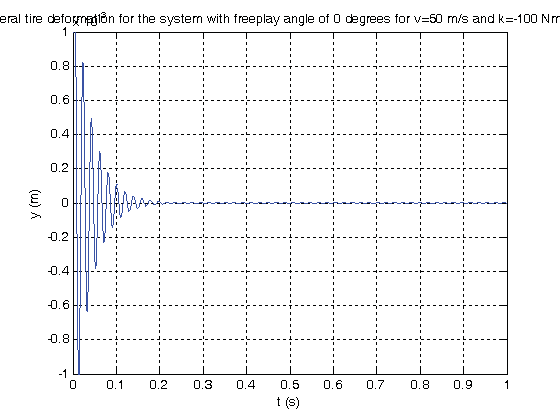
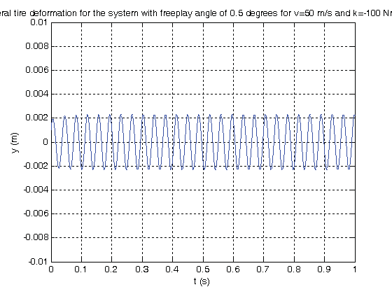
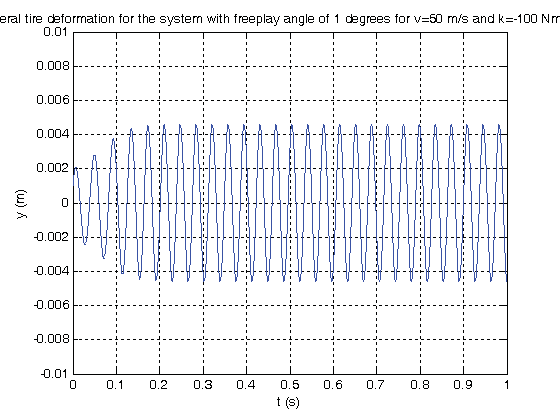
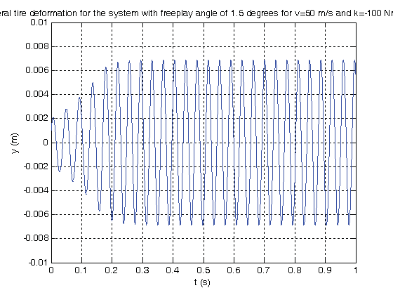
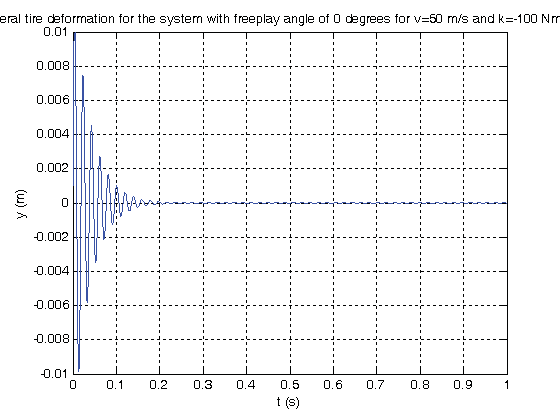
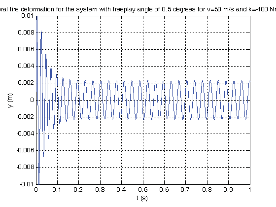
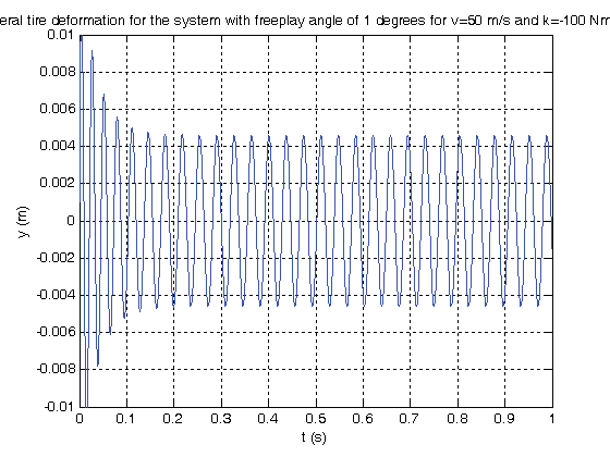
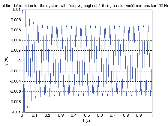
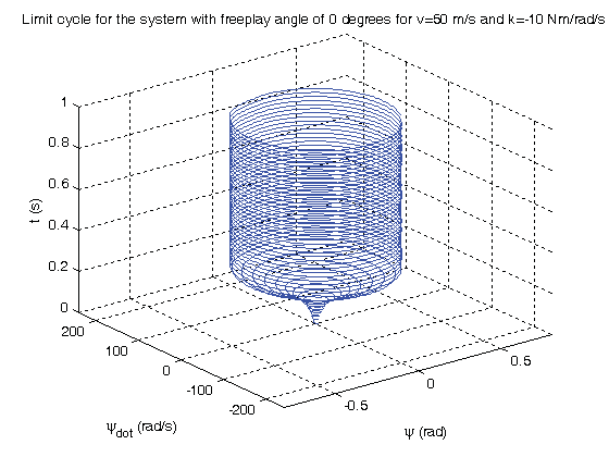
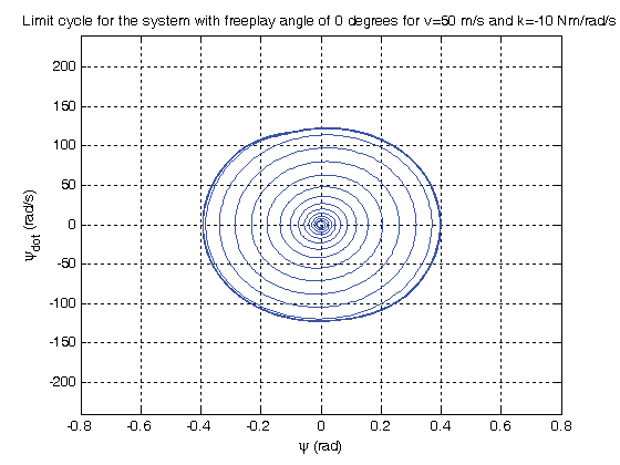
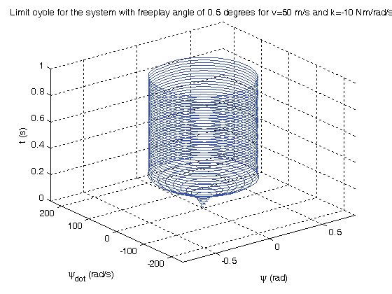
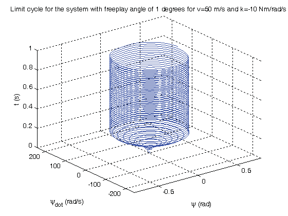
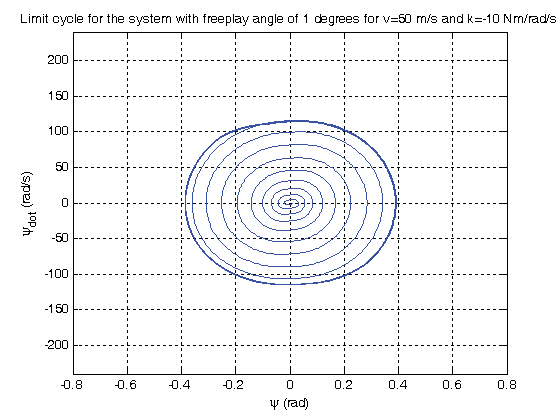
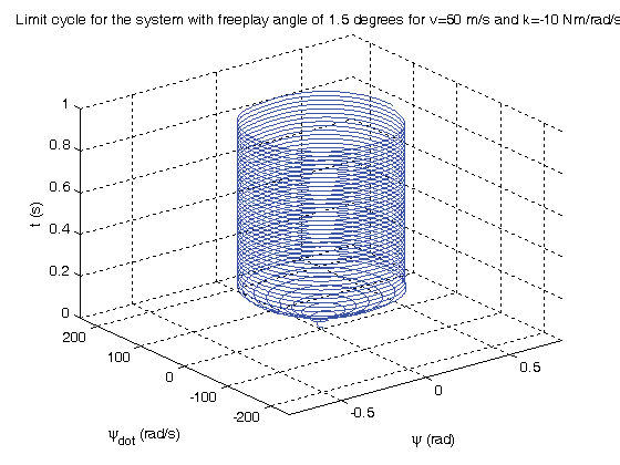
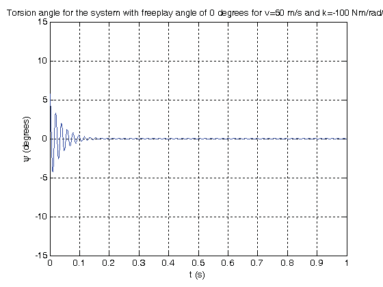
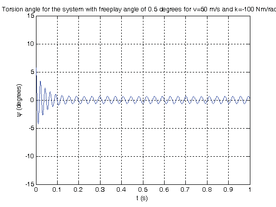
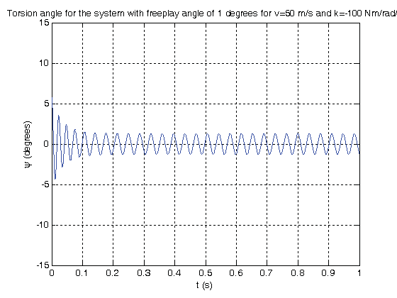
Effects of freeplay are observed by obtaining time histories of the torsion angle and lateral tire deformation and limit cycles. Freeplay angles of 0º, 0.5º, 1º and 1.5º are incorporated. Amplitudes and frequencies of oscillations of the time histories of the ( ) Effect of freeplay on the torsion angle and lateral tire deformation are observed. By observing tables 2-4 it can be stated that the existence of a freeplay angle prevents shimmy damping of the system with the same physical parameters. The increase in the freeplay angle increases shimmy amplitude. A 0.5º increase of the freeplay angle from 0.5º to 1º doubles the amplitude in all 3 cases. Another 0.5º increase in the freeplay angle from 1º to 1.5º causes a 25% increase in the amplitude of the torsion angle and a 55% increase in the amplitude of the lateral tire deformation.
( ) ? ? + ? ? ? ? ? = fp fp fp fp fp fp K K M ? ? ? ? ? ? ? ? ? ? ? ? ? ? if if 0 if ? , ? K fp ? fp ? ? 1 c ( )14. Global Journal of Researches in Engineering
![shimmy system with Coulomb and quadratic damping [28] and amplitudes of limit cycles are predicted.](https://engineeringresearch.org/index.php/GJRE/article/download/101240/version/101240/5-On-Dynamics-of-a-Landing-Gear-Mechanism_html/26466/image-2.png)
![a) Landing gear model In this study, dynamics of a landing gear model with torsional degree of freedom and torsional freeplay is analyzed. The nonlinear mathematical shimmy model presented in[11], [29] and [30] describes the torsional dynamics of the lower parts of a landing gear mechanism and stretched string tire model. Figures1 a and bshow the physical and mathematical nose landing gear models. Dynamics of the lower part of the landing gear is described by a second order ordinary differential equation for the yaw angley about the vertical axis z , while the dynamics of the tire modeled with respect to the stretched string tire model is described by a first order ordinary differential equation for the lateral tire deflection y .](https://engineeringresearch.org/index.php/GJRE/article/download/101240/version/101240/5-On-Dynamics-of-a-Landing-Gear-Mechanism_html/26467/image-3.png)
![Figure 1: a. Nose landing gear model [30], b. shimmy dynamics model [29].](https://engineeringresearch.org/index.php/GJRE/article/download/101240/version/101240/5-On-Dynamics-of-a-Landing-Gear-Mechanism_html/26468/image-4.png)
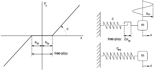
![Figure 2 : Modeling of freeplay [7].](https://engineeringresearch.org/index.php/GJRE/article/download/101240/version/101240/5-On-Dynamics-of-a-Landing-Gear-Mechanism_html/26473/image-9.png)