1.
Abstract-In power system, one most crucial problem is maintaining system stability. The main reasons for occurring stability problem in the system is due to the fault occurs in the system. This paper presents the model of a Unified Power Flow Controller (UPFC) which is externally controlled by a cascade Proportional Integral Differential (PID) controller for the improvements of voltage stability on line power system. The cascade PID controller parameters has been selected by using Tyreus-Luyben settings method for primary loop controller and modified Ziegler-Nichols method for secondary loop controller. Cascade control is mainly used to achieve fast rejection of disturbance before it propagates to the other parts of the plant.PID controller in cascade architecture is the best choice compared to conventional single loop control system for controlling nonlinear processs. The primary controller is used to calculate the setpoint for the secondrary controller. Both single phase and three phase faults have been considered in the research. In this paper, A power system network is considered which is simulated in the phasor simulation method & the network is simulated in three steps; without UPFC, With UPFC but no externally controlled, UPFC with cascade PID. Simulation result shows that without UPFC, the system parameters becomes unstable during faults. When UPFC is imposed in the network, then system parameters becomes stable. Again, when UPFC is controlled externally by cascade PID controllers, then system parameters (V,P,Q) becomes stable in faster way then without controller. It has been observed that the UPFC ratings are only 10 MVA with controllers and 100 MVA without controllers. So, UPFC with cascade PID controllers are more effective to enhance the voltage stability and increases power transmission capacity of a power system. The power system oscillations is also reduced with controllers in compared to that of without controllers. So with cascade PID controllers the system performance is greatly enhanced.
2. Introduction
ACTS can convenience the power flow control, increases the power transfer capability, enhance the security and stability, decrease the generation cost of the power system [1]- [2]. UPFC is one kind of Authors ? ? ?: Dept. of EEE, Rajshahi University of Engineering & Technology, Rajshahi, Bangladesh. e-mails: [email protected], [email protected] FACTs device which can be installed in series in the transmission lines [3]. It is used to control the power flow along the transmission line and thus to meet the needs of power transfer. UPFC consists of a series and shunt converter that is connected by a common DC link capacitor. UPFC performs simultaneously the function of transmission line real and reactive power flow control in addition to UPFC bus voltage shunt reactive power control. The parameters (voltage, impedence, and phase angle) affecting power flow in the transmission line which can be control by using of the UPFC [4]- [6]. The UPFC bus voltage/shunt reactive power and the dc link capacitor voltage is controlled by the shunt converter of the UPFC. The series converter of the UPFC injects a series voltage of adjustable magnitude and phase angle in the transmission line and controls real and reactive power flow in the transmission line [7]- [9]. The dynamic nature of the UPFC lies in the use of thyristor devices (e.g. GTO, IGCT).Therefore, this paper presents thyristor based UPFC controllers to improve the performance of multimachine power system.
3. II.
4. Control Concept of upfc
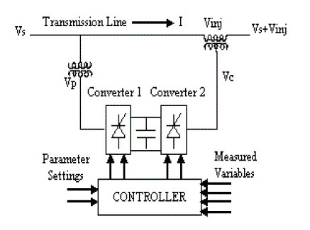
UPFC is a FACTS device used for improving power quality in power systems is shown in fig1.The UPFC consists of combination of series converter and shunt converter. The DC terminals of shunt device are connected to a common link DC capacitor. The shunt converter of the UPFC controls the UPFC bus voltage/shunt reactive power and the dc link capacitor voltage. In this case, the shunt converter voltage is decomposed into two components. One component is in phase and the other in quqdrature with the UPFC bus voltage. Decoupled control system has been employed to achive simultaneous control of the UPFC bus voltage and the DC link capacitor voltage. The series converter of the UPFC provides simultaneous control of real and reactive power flow in the transmission line. The series converter injected voltage is decomposed into two component. One component of the series injected Year 2014 voltage is in quadrature and the other in phase with the controls the transmission line real power flow. This strategy is similar to that of a phase shifter. The in phase component controls the transmission line reactive power flow. This strategy is similar to that of a tap changer.
5. UPFC bus voltage. The quadrature injected component
6. Power System Model
This example described in this section illustrates modeling of a simple transmission system containing 2-hydraulic power plants in Fig. 2. The power grid consists of two power generation substations [10] . Complete simulink model is shown in Fig. 3. A UPFC is used to control the power flow in a 500 kV /230 kV transmission system. The system, connected in a loop configuration, consists essentially of five buses (B1 to B5) interconnected through three transmission lines (L1, L2, L3) and two 500 kV/230 kV transformer banks Tr1 and Tr2. Two power plants located on the 230 kV system generate a total of 1500 MW which is transmitted to a 500 kV, 15000 MVA equivalent and to a 200 MW load connected at bus B3. Each plant model includes a speed regulator, an excitation system as well as a power system stabilizer (PSS). In normal operation, most of the 1200 MW generation capacity of power plant #2 is exported to the 500 kV equivalent through two 400 MVA transformers connected between buses B4 and B5. Complete Simulink model has shown in Fig. 3.
7. IV.
8. Simulation Results
The load flow solution of the above system is calculated and the simulation results are shown below. Two types of faults: A. single line to ground fault &B. Three phase fault have been considered.
9. Designe of Cascade Propotional Integral Differtional Controller (pid)
The Tyreus-Luyben [10] procedure is quite similar to the Ziegler-Nichols method but the final controller settings are different. Tyreus-Luyben PID Controller, the values of delay time, rise time, and settling time are better in comparison with Modified Ziegler-Nichols method. Also this method only proposes settings for PI and PID controllers. These settings that are based on ultimate gain and period are given in table 1. For some control loops the measure of oscillation, provide by ¼ decay ratio and the corresponding large overshoots for set point changes are undesirable therefore more conservative methods are often preferable such as modified Z-N settings.
? + + = Gc(s)=Kp(1+ ?? S i T + S d T )Figure 12 : PID controller is in proportional action For selecting the proper controller parameters, Tyreus-Luyben Tuning Method is described below.
In this method, the parameter is selected as T i =?,T d =0. Using the proportional controller action [Fig. 12]only increase K p from 0 to a critical value K cr. At which the output first exhibits sustained oscillations [Fig. 13]. Thus the critical gain K cr & the corresponding period P cr are experimentally determined.It is suggested that the values of the parameters K p T i T d should set according to the following formula same as Zieglar-Nicles methods. In this method, the parameter is selected as T i =?,T d =0.
10. Simulation Results
The network remains same [Fig. 3
11. R esults & D iscussions
The performance of the proposed PID Controller with UPFC has been summarized in the table-II. In table-II, ? (infinite time) means the system is unstable, UPFC rating in MVA. The network is simulated in three steps; without UPFC, With UPFC, UPFC with proposed PID Controller.
T able 2 : Performance of Proposed PID Controller VIII.
12. C onclusion
This paper presents the power system stability improvement i.e. voltage level, machine oscillation damping, real & reactive power in a power system model of UPFC without or with proposed cascade PID Controller for different types of faulted conditions. Cascade PID is also a very efficient controller then From above results, this proposed Tyreus-Luyben setting method for selecting for primary PID controller parameters and modified Ziegler-Nichols method for Secondary PID controller. In cascade PID Controller may be highly suitable as a UPFC controller because of shorter stability time, simple designed, low cost & highly efficient controller. Rather that, If cascade PID controller is used then only small rating of UPFC becomes enough for stabilization of robust power system within very conditions. These proposed cascade PID Controller can be applied for any interconnected multi-machine power system network for stability improvement. These controller can be applied to another FACTS devices namely SSSC, STATCOM, SVC whose controllers may be controlled externally by designing different types of controllers which also may be tuned by using different algorithm i.e. Fazzy logic,ANN, Genetic algorithm, FSO etc. for both transient and steady state stability improvement of a power system.

![For this demo we are considering a contingency case where only two transformers out of three are available (Tr2= 2*400 MVA = 800 MVA). The load flow shows that most of the power generated by plant #2 is transmitted through the 800 MVA transformer bank (899 MW out of 1000 MW) and that 96 MW is circulating in the loop. Transformer Tr2 is therefore overloaded by 99 MVA. The demonstration illustrates how the UPFC can relieve this power congestion. The UPFC located at the right end of line L2 is used to control the active and reactive powers at the 500Kv bus B3, as well as the voltage at bus B_UPFC. It consists of a phasor model of two 100-MVA, IGBT-based, converters (one connected in shunt and one connected in series and both interconnected through a DC bus on the DC side and to the AC power system, through coupling reactors and transformers). Parameters of the UPFC power components are given in the dialog box. The series converter can inject a maximum of 10% of nominal line to-ground voltage (28.87 kV) in series with line L2. The blue numbers on the diagram show the power flow with the UPFC in service and controlling the B3 active and reactive powers respectively at 687 MW and -27 Mvar. Machines, UPFC parameters value was taken from reference[ 10].](https://engineeringresearch.org/index.php/GJRE/article/download/1011/version/101326/5-Improvement-of-Power_html/28431/image-4.png)
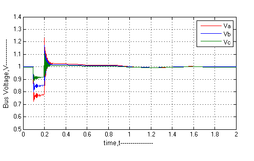
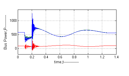
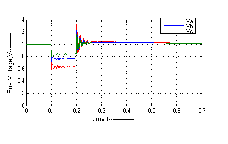
![a) Single line to ground fault Consider a 1-phase fault occurred at 0.1s & circuit breaker is opened at 0.2s (4-cycle fault), Without UPFC, the system voltage, power goes on unstable[Fig.(4,6)]. But if UPFC(without controller) is applied then voltage becomes stable within 1s [Fig.5],power(P,Q) becomes within 1.4s[Fig.(7,8)] . All results has been summarized in table-III.](https://engineeringresearch.org/index.php/GJRE/article/download/1011/version/101326/5-Improvement-of-Power_html/28432/image-5.png)
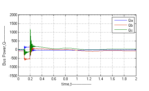
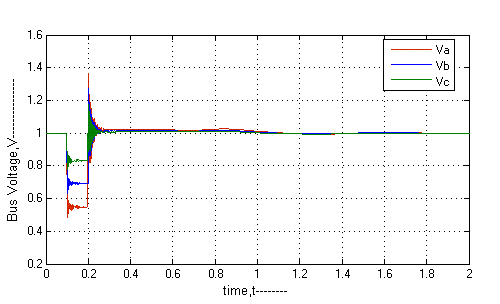
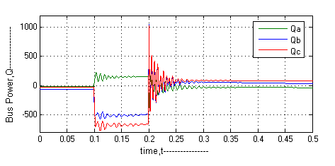
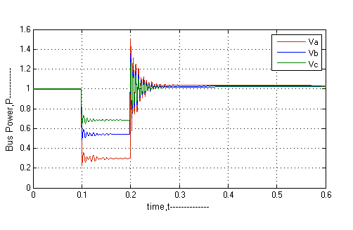
![Figure 8 : Bus Power (Q) in MVAR for 1-phase fault (with UPFC) b) Three phase fault During 3-phase faults, If UPFC is applied then system voltage becomes stable at t=1.2s [Fig.9] &Power becomes stable at t=1.6s [Fig.(10,11)].](https://engineeringresearch.org/index.php/GJRE/article/download/1011/version/101326/5-Improvement-of-Power_html/28434/image-7.png)
![K p =0.3125K cr , T i =2.2P cr , T d =0.159P cr Notice that the PID controller tuned by proposed Tyreus-Luyben tuning methods rules as follows, +0.159PcrS) It's found that, P cr =0.2s & K cr =200 [Fig.4]. So, Gc(s)= ??.???? ?? * (??² + ????. ð??"ð??"?? + ????. ð??"ð??") Ziegler-Nichols Tuning Method is described below.](https://engineeringresearch.org/index.php/GJRE/article/download/1011/version/101326/5-Improvement-of-Power_html/28437/image-10.png)
![.14]only increase K p from 0 to a critical value K cr. At which the output first exhibits sustained oscillations [Fig.14]. Thus the critical gain K cr & the corresponding period P cr are experimentally determined.It is suggested that the values of the parameters K p T i T d should set according to the following formula .](https://engineeringresearch.org/index.php/GJRE/article/download/1011/version/101326/5-Improvement-of-Power_html/28438/image-11.png)
![K p =0.2K cr , T i =0.5P cr , T d =0.33P cr Notice that the PID controller tuned by proposed Ziegler-Nichols tuning methods rules as follows+0.33PcrS) It's found that, P cr =0.2s & K cr =200[Fig.4]. So, Gc(s)= ??.ð??"ð??"?? ?? * (??² + ??ð??"ð??"?? + ??ð??"ð??"??) VI.](https://engineeringresearch.org/index.php/GJRE/article/download/1011/version/101326/5-Improvement-of-Power_html/28439/image-12.png)
| Controller | Kp | Ti | Td |
| PI | Kcr/3.2 | 2.2Pcr | |
| PID | Kcr/3.2 | 2.2Pcr | Pcr/6.3 |
| Controller | Kp | Ti | Td | ||||||||||||
| PI | 0.2Kcr | Pcr/2 | |||||||||||||
| PID | 0.2Kcr | Pcr/2 | Pcr/3 | ||||||||||||
| a) Designed of PID Controller | |||||||||||||||
| PID controller is tuned by the proposed | |||||||||||||||
| Tyreus-Luyben tuning methods.The PID controller has | |||||||||||||||
| three term control signal | |||||||||||||||
| u | t ( | ) | K | p | e(t) | i T K p | e | t ( | ) | dt | K | p | T d | dt t de ( | ) |