1. Introduction
n long-haul point-to-point optical fiber communication the signal traveling inside the fiber suffers from various losses like fiber attenuation losses, fiber tap losses, fiber splice losses, etc., due to these losses it is difficult to detect the original signal at the receiver side. So in order to transmit signal over a long distance in a fiber it is necessary to compensate all losses in the fiber. The introduction of optical amplifiers allowed the signal amplification in optical domain. There was no need to convert the optical signal to electrical signal. There are mainly two types of optical amplifiers: semiconductor optical amplifier and fiber amplifiers. Fiber amplifiers are classified as erbium doped fiber amplifier (EDFA), Raman amplifier and Brillouin amplifier.
EDFA is made by a popular material for longhaul telecommunication applications that is a silica fiber doped with erbium (Er +3 ) ions [1,2]. Er +3 ions are having the optical fluorescent properties that are suitable for the optical amplification. The advent of EDFA has enable the optical signals in an optical fiber to be amplified directly in high bit rate systems beyond Terabits. One of the most important factors limiting the transmission distance in fiber optical communication systems is the optical power loss caused by scattering and absorption mechanisms in optical fiber [4,7].
EDFA is suitable to operate at the conventional (C) band from about 1530 to 1565 nm. Since the entire C band of EDFA is fully utilized, the need for more optical channels and wider optical bandwidth urges EDFA technology to develop beyond its present limits. To extend the optical bandwidth and increase the number of WDM channels, L-band optical amplifiers are used to operate in longer wavelength from about 1570 to 1605 nm. EDFA by itself has a very lowgain at the L-band, most realizations of L-band EDFA implement a long length of erbium-doped fiber (EDF) to pump up its gain. A typical L-band EDFA also has larger noise figure than C-band EDFA. Unlike EDFA have the problems of un pumped amplifier attenuations and the operation wavelength constrained at 1.53-1.56 µm region, Raman fiber amplifier (RFA) has merit of arbitrary gain bandwidth, which were recently being recognized as an enabling technology for high capacity and long-haul density wavelength-divisionmultiplexing (DWDM) systems. RFA can be used to amplify not only the C-band, but also the S-, L-and other bands, depending on the usage of the pumped wavelengths. RFA has several advantages including lower noise figure (NF), flexibility on the selection of gain medium, and wide gain bandwidth, especially that RFA has the capability to "distribute" the gain over a long distance in the transmission fiber. Thus, L-band optical amplifier is better to adopt RFA rather than L band EDFA [11]. As EDFA can operate in a broad range within the 1550 nm [9,10] window at which the attenuation of silica fiber is minimum and therefore it is ideal for the optical fiber communication systems operating at this wavelength range. Hence it is very useful in WDM for amplification. According to the research performed in recent years, it is known that the pumping of EDF at 980 nm or 1480 nm is the most efficient way. High gain (30~50dB), large bandwidth (>90 nm), high output power (10~20 dBm) and low NF (3~5 dB) can be obtained using an EDFA optimized for 1550 nm range [3,5].
2. II.
3. EDFA Architecture
An optical fiber consists of a doped fiber, one or more pump lasers, a passive wavelength coupler, optical isolators, and tap couplers. The wavelength selective coupler couples both the pump and signal optical power efficiently into the fiber amplifier. The tap couplers are wavelength insensitive and are generally used on both sides of the amplifier to compare the incoming signal with the amplifier output. The optical isolators prevent the amplified signal from reflecting back into the device, where it could increase the amplifier noise and decrease its efficiency [2]. Typically, the EDFA configuration can be categorized by pumping schemes into three particular arrangements. These schemes are Forward-pumped (co-pumped), Backwardpumped (counter-pumped), and Bidirectional-pumped (Dual-pumped) [6]. Pumping at a suitable wavelength provides gain through population inversion the gain spectrum depends on the pumping scheme as well as on the presence of other dopants, such as germanium and alumina, within the fiber core [1,6]. In forward pumping, figure 1, the input signal and the pump signal propagate in the same direction inside the fiber [2]. The input signal and pump are combined using a pump combiner or wavelength selective coupler. Inside the fiber the pump energy is transferred to the input signal and the signal is amplified at the output of the amplifier. Isolators are used in the scheme to make sure that the signal will travel only in one direction and no feedback of signal will occur.
In backward pumping, figure 2, the input signal and the pump signal propagate in the opposite direction to each other inside the fiber.
In Bi-directional pumping, figure 3, the input signal travels in one direction. But the there are two pump signals that travel inside the fiber. One pump signal travels in the same direction as the input signal and the other pump signal travels in the opposite direction to that of the input signal.
4. Pump wavelength 980nm
Er +3 ion density 1e+025 m -3 This paper focuses on the performance characteristics of the amplifier (gain and NF) assuming the fundamental LP 01 mode exciting at the pump wavelength (?p= 980 nm) [6]. The gain and NF can be obtained for all the three pumping configurations as a function of two fundamental fiber parameters namely: fiber length, and pump power. Thus, the required fiber parameters and pump power values can be optimized for a desired EDFA gain-NF performance at 10 and 40 Gbps. The main parameters of the simulation are shown in Table I.
IV.
5. Results & Discussion
In this paper the variation of Gain and NF for EDFA is analyzed with different pumping techniques i.e. forward pumping, backward pumping and bidirectional pumping. And also the variation of gain and NF is analyzed for different EDF length (10,30, & 50 m) and at different pumping power (10, 50 & 100 mW). The length of the EDF depends upon the input signal power, pump power, Er +3 ion density and the signal and pump wavelength.
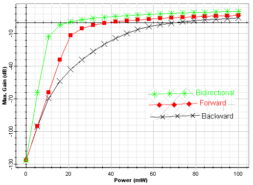
6. a) Gain Characteristics
The gain of different pumping configuration is varied along with the fiber length is shown in figures 4, 5, and 6 at different pump powers 10, 50, and 100 mW, respectively, having a constant signal input power, Er +3 ion density, signal wavelength, and pump wavelength. Form the figures it is seen that the maximum gain flatness is obtained for a wider range of fiber length in case of bidirectional pumping configuration at a higher pump power of 100 mW. On comparing the graphs it can be concluded that in case of bidirectional pumping configuration as the fiber length is increased the pump power should be increased to obtain higher value of gain and its flatness for higher range of fiber length. Whereas backward pumping gives the worst results but forward pumping shows acceptable results but values are less than bidirectional pumping configuration. If the Er +3 ion density is decreased to 1e+024 m -3 forward and backward pumping configurations gives flat gain for fiber length range which is less as compared to the Er +3 density of 1e+025 m -3 for bidirectional pumping configuration. From the figures 10, 11, and 12 the bidirectional and forward pumping configuration gives miminum NF at the pump power of 100mW as compare to backward pumping configuration. Also from the figures 13, 14, and 15 in the case of bidirectional and forward pumping configuration the minimum NF is obtained at the fiber length of 30m for a wide range of pump power. But as the fiber length increases pump power should also be increased to minimize NF. Thus when the pump power increases the minimum NF is achieved at the fiber length of 30m for forward and bidirectional pumping configuration. But the Er +3 ion density is kept at 1e+024 m -3 then as the fiber length increases the NF increases even if the pump power is increased. Hence the Er +3 ion density is set as 1e+025 m -3 . This paper gives the comparison of the three pumping configurations, i.e., forward, backward, and bidirectional pumping based on gain and NF at different pump power (10, 50, & 100mw) and at different fiber length (10, 30, & 50m) operating in C-band, 10dBm signal input power, 980nm pump wavelength, and Er +3 ion density of 1e+025 m -3 . It is found that the minimum NF occurs for both forward and bidirectional pumping configuration whereas flat gain is obtained by using bidirectional pumping configuration. Thus bidirectional pumping configuration can be said to be the best configuration. It is also seen that when the fiber length increases the pump power should be increased in order to achieve the flat gain and minimum NF by maintaining the Er +3 ions density at higher value. Also any increase in data rate doesn't cause any change in the results of all the configurations. This paper shows that although the flat gain is achieved but efforts must be done to increase the value of gain.