1. Introduction
Multilevel inverter is based on the fact that sine wave can be approximated to a stepped waveform having large number of steps. The steps being supplied from different DC levels supported by series connected batteries or capacitors. The unique structure of multilevel inverter allows them to reach high voltages and therefore lower voltage rating device can be used. As the number of levels increases, the synthesized output waveform has more steps, producing a very fine stair case wave and approaching very closely to the desired sine wave. It can be easily understood that as motor steps are included in the waveform the harmonic distortion of the output wave decrease, approaching zero as the number of levels approaches infinity.
Hence Multi-level inverters inverters offer a better choice at the high power end because the high volt-ampere ratings are possible with these inverters without the problems of high dv/dt and the other associated ones [5].
Nowadays different topologies have been reported for multi-level inverters. They are named as neutral point clamped (diode-clamped) inverter, flying capacitor (capacitor-clamped) inverter and cascaded multi-cell with separated dc source inverter [6]. Among them, the FCMLI does not require isolated DC sides and additional clamping diodes, the snubberless operation is possible and it is easy to be expanded to the multilevel. The FCMLI offers a great advantage with respect to the availability of voltage redundancies. This inverter uses capacitors to limit the voltage of the power devices. They are defined as different combinations of capacitors allowing the charging or discharging of the individual flying capacitors in order to produce the same phase leg voltage. This advantage provides the special opportunity for controlling the individual voltage on flying capacitors [6]- [7]. Many studies have shown that under certain conditions, a simple open loop control guarantees natural balancing of the flying capacitor. n Recent years, there has been an increasing interest in electrical power generation from renewable-energy sources, such as photovoltaic (PV) or wind-power systems [1], [2]. The benefits of power generation from these sources are widely accepted. They are essentially inexhaustible and environmentally friendly. Among the different renewable-energy sources possible to obtain electricity, solar energy has been one of the most active research areas in the past decades, both for gridconnected and stand-alone applications [3]- [4]. clamped DC-DC boost converter have been proposed. This scheme maintains the output voltage stability, reducing the harmonic content in the output there by improving the overall system performance. This paper has been designed using a seven level flying capacitor multilevel inverter with the appropriate closed loop schemes there by THD can be significantly reduced which is confirmed through simulation investigation. For this proposed topology, DC input to the system is a solar energy which is harvested from the Sun based on the irradiation and insolation level. In this system a single stand-alone PV module of 12V capacity is used to obtain the DC voltage. Then this obtained DC voltage is given as the input to the Capacitor Clamped DC-DC Boost Converter. By the boost DC-DC converter topology, the 12V DC is boosted into 48V DC.
In order to maintain the constant DC voltage from the boost converter, a closed loop block is designed in which the actual DC voltage is compared with the 48V DC set value. Based on the error signal Then based upon the specified switching frequency of MOSFET, switching pulses are given to the single switch in the boost converter. Then the boosted DC voltage is given as the input to the seven level FCMLI which is used for 48V DC to 48V AC conversion.
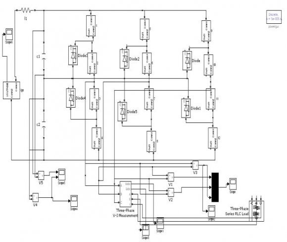
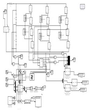
For The overall Simulation diagram of the proposed closed loop system for FCMLI is shown in Figure 2. The difference between the MBC and the conventional one is that in the MBC, the output is Vc times N, where N+1 is the converter's number of levels taking into account the zero level as shown in Figure 3. This behavior is achieved, thanks to the voltage multiplier in the boost converter's output that is driven by the only switch in the converter.
2. IV. Flying Capacitor Multilevel Inverter (FCMLI) a) Basic Configuration
The FCMLI requires a large number of capacitors to clamp the device (switch) voltage to one capacitor voltage level. Provided all the capacitors are of equal value, the size of the voltage increment between two consecutive legs of the clamping capacitors defines the size of voltage steps in the output waveform, if the voltage of the main dc-link capacitor is Vdc the voltage of the innermost capacitor clamping the innermost two devices is Vdc/ (n-1).
The voltage of the next innermost capacitor will be Vdc/(n-1) + Vdc/ (n-1) = 2 Vdc/(n-1) and so on. Each next clamping capacitor will have the voltage increment of Vdc/(n-1) from its immediate inner one. The voltage levels and the arrangements of the flying capacitors in the FCMLI structure assures that the voltage stress across each main device is same and is equal to Vdc/(n-1) for an n-level inverter. V.
3. Results and Analysis
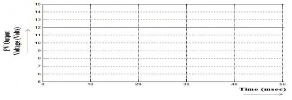
The proposed topology of closed loop system for Flying Capacitor Multilevel Inverter (FCMLI) consists of various models. The corresponding output voltage waveform of 12V PV Panel is shown in the Figure 6. Here Multicarrier PWM in turn PD-PWM technique is employed for generating appropriate PWM pulse for respective switches the MLI.
The Figure 10 shows the Pulse Generation Model Using Multicarrier PWM -PDPWM technique for Seven Level FCMLI. III.
4. Model
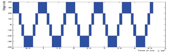
The Figure 12 shows the comparison of six number of carrier signals and the sinusoidal modulating signal. In which the sinusoidal signal is superimposed over the carrier signals for generating appropriate PWM pulses. The Figure 12 shows the comparison of six number of carrier signals and the sinusoidal modulating signal. In which the sinusoidal signal is superimposed over the carrier signals for generating appropriate PWM pulses. In order to reduce the THD level of MLI output a closed-loop model is developed and its corresponding output voltage is shown in Figure 17. The Figure 18 shows the corresponding output voltage waveform of a step-up transformer (48/230V AC). This AC voltage is fed to the Single Phase Lamp Load. The Total Harmonic Distortion (THD) is used to characterize the linearity of audio systems and the power quality of electric power systems.
5. S. No
6. Carrier
The formula below shows the calculation for THD on a voltage signal. The end result is a percentage comparing the harmonic components to the fundamental component of a signal. The higher the percentage, the more distortion that is present on the mains signal. (1)
From the Figure 19, it is observed that THD value of 37.15% is obtained for Open-Loop Multilevel Inverter. This value can be reduced by Closed-Loop design.
The result of THD analysis performed for closed-loop systems is shown in Figure 20.
7. Conclusion
Thus the investigation study for seven level FCMLI was performed with / without closed-loop feedback schemes.
In the proposed method, a closed-loop system was implemented for a Seven Level FCMLI. The newly developed design will improve the system performance and maintains the voltage stability there by stable operation can be ensured without more disturbances. The closed loop controller is also designed for Capacitor Clamped DC-DC Boost Converter there by constant output voltage at the output of the boost converter can be achieved.
The performance was verified through simulation models by using MATLAB software tool. From the simulation study, the important conclusions are, Investigation Report:
The main inference from the proposed concept is, for the developed Seven Level FCMLI system the THD value of open-loop model is 37.15% and for the closed-loop model is 10.18%. Thus the percentage of THD value can be minimized by implementing the closed-loop control for FCMLI there by better performance in its output can be achieved.


![[0 0.005/20 0.01/20 0.015/20 0.02/20] [-1.5 -2 -1.5 -2 -1.5]](https://engineeringresearch.org/index.php/GJRE/article/download/100267/version/100267/1-An-Investigation-Study-of-Total-Harmonic_html/5593/image-15.png)
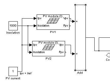
| voltage AC signal of 48V AC is given to the step-up transformer for stepping up the voltage level to 230V AC. Finally a resistive load -single phase lamp load is connected across the 230V AC output terminals. b) System Composition The described system in this paper is a standalone system which consisting of the following individual systems : -i. For generating the DC voltage signal, a suitable stand-alone PV module is used. ii. For boosting up the generated DC voltage, an appropriate Capacitor Clamped DC-DC boost converter is used. iii. For maintaining the constant DC output from boost converter, a closed loop controller is used for DC-DC converter. An Investigation Study of Total Harmonic Distortion in a Flying Capacitor Multilevel Inverter With / from the comparator, the PID controller produces the II. Proposed Topology of Closed Loop System a) Architecture of Proposed System In this paper, Proportional-Integral-Derivative (PID) controllers based closed loop system for seven level flying capacitor multilevel inverter and for capacitor iv. |
| control signal to the PWM pulse generator block. |
| controlling the FCMLI, a closed loop block |
| is designed which consists of voltage measurement, |
| voltage controller -PID controller and Sin generator |
| block. With the help of these blocks, a closed loop |
| design is achieved for proposed FCMLI. Then this low |
| Module | |||
| S. No | Parameters | Specifications | Units |
| 1 | Short Circuit Current (Isc) | 5.45A | Amperes |
| 2 | Open Circuit Voltage (Voc) | 12V | Voltage |
| 3 | Current at Pmax | 4.95A | Amperes |
| 4 | Voltage at Pmax | 17.2V | Voltage |
| 5 | Insolation | 1000 W/m 2 (Constant) | Watts / metre 2 |
| Seven Level Flying Capacitor Multilevel Inverter | ||
| Feedback Schemes | With Closed-Loop Scheme | Without Closed-Loop Scheme |
| Total Harmonic | ||
| Distortion (THD) in | 10.18% | 37.15% |
| percentage | ||